by Angela
Share

An RF attenuator performing poorly can mess up your whole system. How do you know if that little component is actually doing its job right? Let’s look at how you can check.
To test an RF attenuator’s accuracy, you typically use a Vector Network Analyzer (VNA). First, calibrate the VNA system. Then, measure the S21 (insertion loss) across the frequency range to see the actual attenuation. Also, check S11 (return loss) for good impedance matching.
Understanding these steps is key. But knowing why they matter and what good results look like helps you trust your measurements and your components. Let’s dive into the details.
Why Does Attenuator Accuracy Even Matter?
Relying just on the label of an attenuator can be risky. What really happens if its actual performance is off? Bad data and unstable systems often follow.
Inaccurate attenuators cause serious problems. They lead to wrong system calibrations, worse signal quality (SNR), and impedance mismatches, which makes your entire setup unreliable.
The Real Impact of Bad Attenuation
When an attenuator doesn’t meet its specification, the consequences can ripple through your design or test setup. Let’s break down the main issues:
-
Misleading System Calibration: If you’re using an attenuator in a test setup to calibrate power levels or receiver sensitivity, an error directly translates into an incorrect calibration. For example, if you think you’re reducing a signal by 10 dB but it’s actually only 9 dB, all subsequent measurements based on that calibration will be wrong. I remember one project [Placeholder for a story about a calibration error causing issues] where a faulty attenuator cost us days of re-testing.
-
Degraded Signal-to-Noise Ratio (SNR): In receiver systems, attenuators might be used to prevent overloading sensitive components. If the attenuation is less than expected, the component could still overload or saturate. If the attenuation is more than expected, it might push weak signals closer to the noise floor, making them harder to detect accurately. This directly impacts system sensitivity.
-
Impedance Mismatch and Instability: Attenuators should ideally pass signals through with the specified loss while maintaining the system’s characteristic impedance (usually 50 ohms). A poorly designed or faulty attenuator can have bad return loss (high S11). This means signal power reflects back towards the source, causing instability, inaccurate power transfer, and potentially even damaging sensitive source components.
| Here’s a simple table showing the effects: | Issue | Consequence |
|---|---|---|
| Calibration Error | Incorrect measurements, bad system tuning | |
| Low SNR | Difficulty detecting weak signals, reduced range | |
| Impedance Mismatch | Signal reflections, power loss, instability |
Ensuring accuracy is vital in everything from basic lab tests to complex communication systems.
What Equipment Do You Need for Accurate Testing?
Just guessing if your attenuator works correctly isn’t good enough. Using the wrong tools or setup will give you results you can’t trust. So, what gear do you really need for precise testing?
The best tool is a Vector Network Analyzer (VNA). Alternatively, you can use a Signal Generator plus a Spectrum Analyzer. You also absolutely need quality RF cables, connectors, and a calibration kit matching your VNA.
Gathering Your Test Toolkit
Having the right instruments is the first step towards reliable attenuator testing. Here’s a closer look at the essential items and why they matter:
-
Vector Network Analyzer (VNA): This is the preferred instrument. A VNA measures complex S-parameters (like S21 and S11) across frequency. It directly tells you insertion loss (attenuation) and return loss (impedance match). We rely heavily on our VNA in the lab for component verification.
-
Signal Generator + Spectrum Analyzer: If you don’t have a VNA, this pair can work. The signal generator produces a test signal at known frequencies and power levels. The spectrum analyzer measures the power level after the attenuator. You compare the input and output power to find the attenuation. It’s less direct than a VNA, especially for return loss.
-
Calibrated RF Cables and Connectors: Your test cables become part of the measurement. Using high-quality, phase-stable cables minimizes errors. Cheap or damaged cables introduce extra loss and reflections, skewing your results. We always use semi-rigid or high-performance flexible cables for critical measurements.
-
Calibration Kit: This is crucial when using a VNA. A cal kit contains known standards (Short, Open, Load, Thru – SOLT). Running a calibration routine with the kit allows the VNA to mathematically remove the effects of the cables and connectors from the measurement, so you only see the performance of the attenuator itself.
-
Matching Impedance: Ensure all components (VNA ports, cables, attenuator) have the same characteristic impedance, usually 50 ohms for most RF work.
| Here’s a quick summary of the gear: | Equipment | Purpose | Importance |
|---|---|---|---|
| VNA | Measures S21 (Loss) & S11 (Match) directly | Highest | |
| Sig Gen + Spectrum Analyzer | Measures power levels to calculate loss | Alternative | |
| Quality Cables/Connectors | Minimize test setup error | High | |
| Calibration Kit | Removes cable/connector effects (for VNA) | Essential |
Optional gear like a power meter can verify absolute power levels, but the VNA/SA setup is usually sufficient for checking attenuation accuracy relative to the input.
How Do You Measure Attenuation and Return Loss Properly?
Okay, you have the equipment. Just connecting the attenuator isn’t the whole story. If you don’t perform the measurement correctly, your results might still be wrong. How do you get trustworthy data?
First, always calibrate your VNA system right at the points where the attenuator will connect. Then, measure S21 across the frequency band to get the actual attenuation (insertion loss). Don’t forget to measure S11 (return loss) too.
Performing the Key Measurements: S21 and S11
Let’s walk through the practical steps using a VNA, which gives the most complete picture:
-
Calibration: This is non-negotiable for accuracy. Perform a full 2-port calibration (SOLT – Short, Open, Load, Thru) using your calibration kit. Connect the cal standards directly to the ends of the test cables where your attenuator will later be connected. This tells the VNA to ignore the losses and reflections from the cables themselves.
-
Measure S21 (Insertion Loss / Attenuation):
- After calibration, connect the attenuator between the VNA’s Port 1 and Port 2 using your test cables.
- Set the VNA to measure S21 over the attenuator’s specified frequency range (e.g., DC to 6 GHz).
- The VNA display will show a plot of S21 (in dB) versus frequency. This value represents the power lost as the signal passes through the attenuator. For a 10 dB attenuator, you expect this value to be close to -10 dB.
-
Measure S11 (Return Loss / Impedance Match):
- While the attenuator is connected, set the VNA to measure S11.
- This measures how much power is reflected back from the attenuator’s input port due to impedance mismatch.
- The S11 value is usually shown in dB. A larger negative number is better. For example, -20 dB means only 1% of the power is reflected. We typically look for S11 to be better (more negative) than -20 dB across the band. This corresponds to a Voltage Standing Wave Ratio (VSWR) of less than 1.22.
-
Analyze the Results:
- Compare the measured S21 value to the attenuator’s nominal value (e.g., 10 dB). Check if it’s within the specified tolerance (e.g., ±0.5 dB).
- Examine the S21 plot for flatness across the frequency range.
- Check if the S11 (return loss) meets the specification (e.g., >20 dB).
| Here’s how you might record basic results: | Frequency (GHz) | Measured Attenuation (S21 dB) | Return Loss (S11 dB) |
|---|---|---|---|
| 1.0 | -9.98 | -25.2 | |
| 3.0 | -10.01 | -23.8 | |
| 6.0 | -10.15 | -21.5 |
These steps give you a clear picture of how the attenuator truly performs.
What Other Factors Affect Reliable Test Results?
Even with the right gear and following the main steps, small details can trip you up. Perfect equipment setup isn’t foolproof. What often overlooked factors can skew your results and how do you avoid them?
Always use high-quality, phase-stable RF cables, not just any patch cord. Keep connectors meticulously clean and tighten them correctly using a torque wrench. Also, check attenuation flatness over the entire frequency band.
Fine-Tuning for Reliability
Getting consistent, trustworthy results requires attention to detail beyond just connecting the VNA. Here are factors we always keep in mind in our lab:
-
Cable Quality Matters: Cheap, overly flexible cables can have unstable loss and phase characteristics, especially at higher frequencies or if flexed during measurement. Using semi-rigid or high-performance phase-stable cables provides much more repeatable results. The difference can be surprising, especially above a few GHz.
-
Connector Care is Crucial: Dirty or damaged connectors are a major source of error.
- Cleanliness: Use isopropyl alcohol and lint-free swabs to clean connector mating surfaces before connecting. Even tiny amounts of dirt or oil can cause significant reflections and loss.
- Torque: Connectors like SMA have a specified torque value. Under-tightening leads to poor electrical contact and reflections. Over-tightening can damage the connector permanently. We always use calibrated torque wrenches appropriate for the connector type. [Placeholder for a story about connector torque solving an intermittent issue].
-
Check Attenuation Flatness: Don’t just check the attenuation at one frequency point. An attenuator might be accurate at 1 GHz but way off at 6 GHz. Look at the S21 plot across the entire specified operating band. Good attenuators should have minimal variation (e.g., less than ±0.5 dB variation from the average attenuation). Significant tilting or ripple in the S21 trace indicates potential issues.
-
Temperature Stability: RF component performance can drift slightly with temperature. Ensure your test environment and the attenuator itself are at a stable temperature, especially for very high precision measurements. Allow equipment to warm up before calibration and testing.
-
Track Individual Units: Manufacturing tolerances mean even attenuators with the same part number might vary slightly. If you have multiple units, it’s good practice to label and test them individually, especially for critical applications. Don’t assume they are all identical.
Paying attention to these details separates a quick check from a reliable, traceable measurement.
Conclusion
Testing RF attenuator accuracy isn’t complex, but it needs the right tools like a VNA, careful calibration, and attention to measuring both S21 loss and S11 match properly.
STAY IN FOR MORE NEWS
Subscribe to our free newsletter.

Introduction RF connectors are essential components used in communication systems to transmit high-frequency signals. Among the many types of RF connectors available, SMA connectors and N type connectors are two of the most widely used. Both connectors are designed for coaxial cable connections, but they differ significantly in size, frequency performance, power handling capability, and
Introduction RF connectors are essential components in modern communication and electronic systems. They are designed to connect coaxial cables to various RF devices while maintaining signal integrity and minimizing signal loss. From wireless communication and satellite systems to test equipment and radar technology, RF connectors play a critical role in ensuring reliable transmission of high-frequency
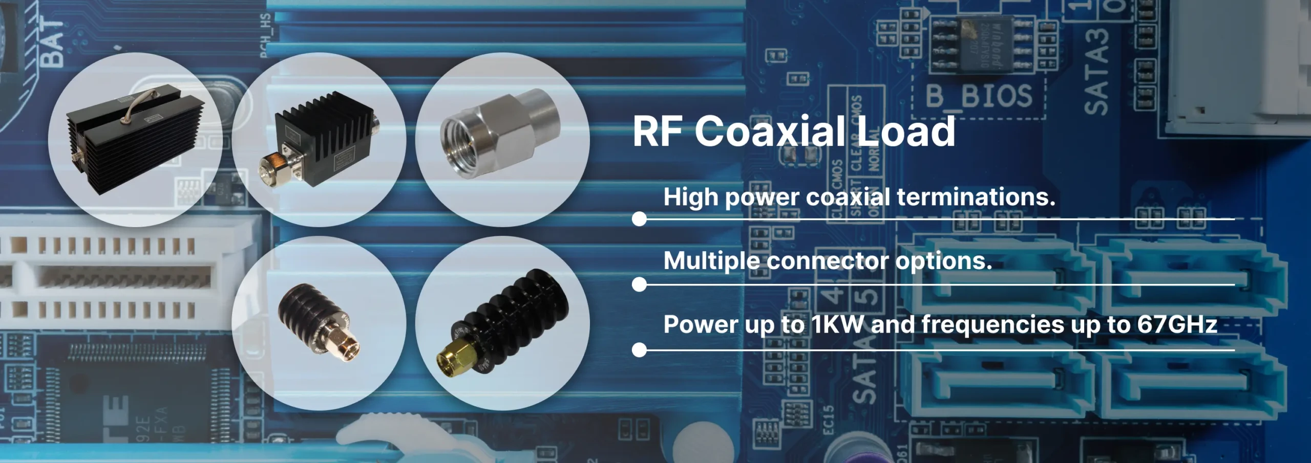
Discover Reach-Line’s precision RF and microwave terminations covering DC to 110 GHz and power levels 1 W to 1000 W. Reliable, low VSWR solutions for 5G, satellite, and lab applications.

Reach-Line offers high-frequency cable assemblies, fixed attenuators, and precision terminations. Partner for engineering support, rapid prototyping, and global logistics.