by Angela
Share

Struggling with signal loss in your RF system? Picking the wrong transmission line between waveguide and coax can degrade performance and cost you dearly. Let’s compare them clearly to help you choose.
Waveguides offer lower signal loss, especially above a few GHz, and handle higher power. Coaxial cables are flexible, easier to install, and work over wider frequency bands from DC up. Your choice depends on frequency, power, loss budget, and installation needs.
Choosing between these two isn’t always simple. The best option depends heavily on what you need your system to do. Let’s break down the specifics so you can make the best decision for your setup and select the right components, whether it’s waveguide sections or high-performance coaxial cable assemblies.
What are the advantages of waveguides over coaxial lines?
Are you pushing high power levels that risk damaging your cables? Or maybe losing too much signal strength over long runs? Waveguides directly address these critical challenges effectively.
Waveguides generally have much lower signal loss (attenuation) per unit length compared to coaxial cables, especially at microwave and millimeter-wave frequencies. They can also handle significantly higher power levels and offer excellent electromagnetic interference (EMI) shielding.

Dive Deeper into Waveguide Benefits
Let’s look closely at why waveguides outperform coax in certain areas.
-
Lower Signal Loss: Coaxial cables suffer from losses in the center conductor, the outer shield (due to skin effect, where current crowds near the surface at high frequencies), and the dielectric material separating them. As frequency increases, these losses climb rapidly. Waveguides, being hollow pipes (often air-filled or gas-filled), eliminate the conductor loss and drastically reduce dielectric loss. This means more of your signal reaches its destination, which is critical in sensitive receivers or long-distance links like satellite ground stations. I remember working on a 20 GHz link where switching from the best low-loss coax to a standard waveguide cut the signal loss by more than half over 10 meters.
-
Higher Power Handling: The large, smooth interior surface area of a waveguide distributes the electrical current better than the small center conductor of a coax cable. This, combined with the absence of a potentially heat-sensitive dielectric core, allows waveguides to handle kilowatts or even megawatts of power, common in radar transmitters or industrial heating applications. Coaxial cables have power limits determined by the heat buildup in the center conductor and dielectric breakdown voltage.
-
Superior Shielding: A waveguide is essentially a continuous metal tube. This inherent structure provides excellent shielding, preventing signals from leaking out and external interference from getting in. While high-quality coaxial cables have good shielding, waveguides are generally superior, especially at very high frequencies.
Here’s a quick comparison table:
| Feature | Waveguide | Coaxial Cable |
|---|---|---|
| Signal Loss | Very Low (especially > 5 GHz) | Moderate to High (increases w/ freq) |
| Power Handling | Very High | Low to Moderate |
| Frequency | Band-limited (has cutoff freq) | Broadband (DC to high GHz) |
| Shielding | Excellent | Good to Very Good |
| Flexibility | Rigid | Flexible |
| Cost | Generally Higher (esp. installation) | Generally Lower |
These advantages make waveguides the preferred choice for applications demanding maximum efficiency and power capability at high frequencies.
What is the difference between waveguide and coaxial line as transmission lines for microwaves?
Are your microwave signals behaving unexpectedly in your system? Using the wrong type of transmission line for these high frequencies could be the root cause of poor performance.
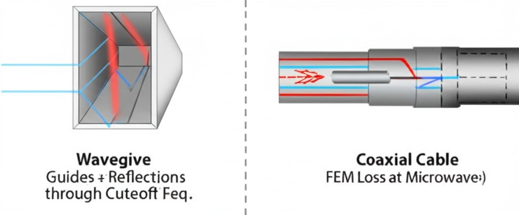
For microwaves, waveguides guide electromagnetic waves within a hollow metal pipe using reflections off the inner walls; they only work above a specific ‘cutoff’ frequency. Coaxial lines use a center conductor and outer shield (TEM mode) and work down to DC, but face increasing losses at microwave frequencies.
Dive Deeper into Microwave Transmission Differences
When we talk about microwaves (roughly 300 MHz to 300 GHz), the way these transmission lines operate becomes quite distinct.
-
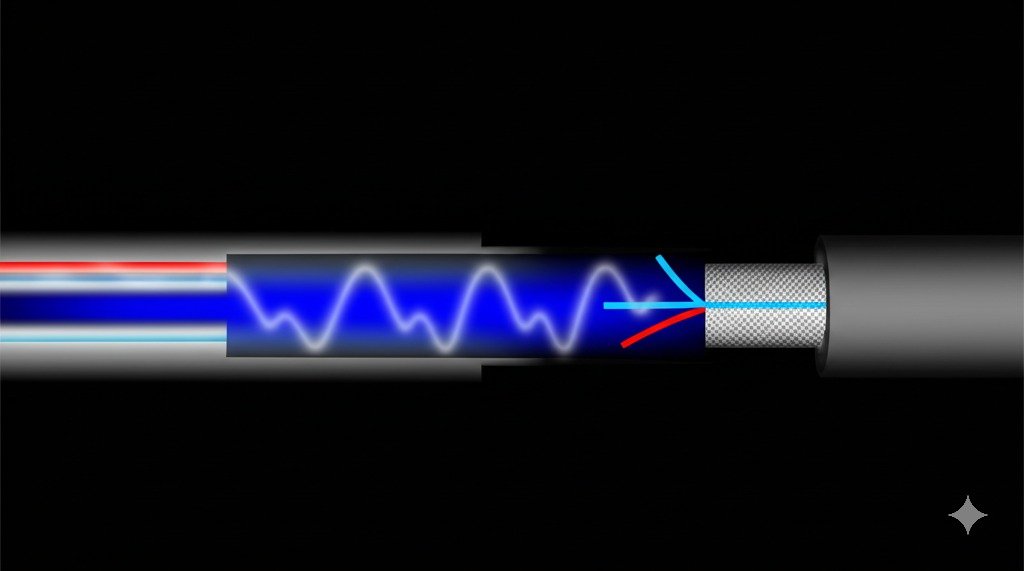
Mode of Propagation: Coaxial cable primarily supports a Transverse Electro-Magnetic (TEM) mode. This means the electric and magnetic fields are perpendicular to the direction the wave travels, similar to light in free space. This mode has no lower frequency limit, which is why coax works down to DC. Waveguides, however, support Transverse Electric (TE) or Transverse Magnetic (TM) modes. Here, either the electric field (TE) or the magnetic field (TM) has a component in the direction of propagation. These modes rely on the wave reflecting off the waveguide walls at specific angles.
-
Cutoff Frequency: A crucial difference is that waveguides have a cutoff frequency. Below this frequency (determined by the waveguide’s dimensions and the mode), the wave cannot propagate efficiently and is rapidly attenuated. Think of it like trying to fit a large object through a small pipe – it just doesn’t work. This means a specific waveguide size is only useful for a particular frequency band. Coaxial cable doesn’t have this sharp cutoff; it works across a wide frequency range, though losses become prohibitive at the very high end.
-
Bandwidth: Because of the cutoff frequency and the potential for higher-order modes at higher frequencies, a given waveguide typically operates effectively over a narrower bandwidth (e.g., 1.5:1 frequency ratio) compared to coaxial cable, which can operate over many octaves.
-
Dispersion: In waveguides, the speed at which the wave travels depends on the frequency (this is called dispersion). In ideal TEM mode coax, the speed is relatively constant across frequencies (determined by the dielectric). Dispersion can distort signals that contain multiple frequencies, like fast digital pulses.
When working with microwave systems, like radar or high-speed data links, understanding these differences is vital. We supply various waveguide components like bends, twists, and terminations, alongside high-frequency coaxial connectors (like 2.92mm, 2.4mm) and cable assemblies designed to minimize loss at these frequencies.
What is the difference between coaxial cable and waveguide?
Confused by how these two components look and feel so different? Their physical construction directly relates to how they handle RF signals, leading to distinct advantages and disadvantages.
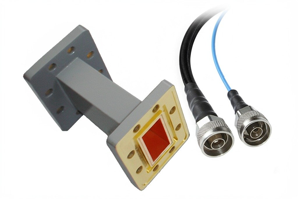
Physically, a coaxial cable consists of a central conductor surrounded by an insulating dielectric, a metallic shield, and an outer protective jacket; it’s typically flexible. A waveguide is usually a rigid, hollow metal tube, often rectangular or circular in cross-section.
Dive Deeper into Physical Construction
Let’s break down their structures:
Coaxial Cable:
- Center Conductor: Usually solid or stranded copper, or copper-clad steel. Carries the signal.
- Dielectric Insulator: Material like Polyethylene (PE), Polytetrafluoroethylene (PTFE), or Foam Polyethylene separates the center conductor from the shield. Its properties heavily influence the cable’s impedance, velocity of propagation, and loss.
- Shield: One or more layers of braided wire (like tinned copper) and/or metallic foil (like aluminum). This prevents signal leakage and interference.
- Outer Jacket: Typically PVC or a more rugged material like Polyurethane, providing environmental protection.
- Flexibility: Most coax types are designed to be flexible, allowing for easy routing around corners (within limits specified by the bend radius).
- Connectors: Uses standard connectors like SMA, N-Type, BNC, TNC, or high-frequency types like 2.92mm, 1.85mm which we offer.
Waveguide:
- Structure: A hollow pipe made of conductive metal like copper, aluminum, or brass. Often plated with silver or gold internally to improve conductivity, especially at higher frequencies.
- Cross-Section: Most commonly rectangular (e.g., WR-90, WR-28 sizes indicate dimensions), but can also be circular, elliptical, or ridged for specific applications.
- Flexibility: Typically rigid. While flexible ("flex") waveguide exists, it usually has higher loss and lower power handling than rigid sections. Installation requires careful planning of runs using pre-fabricated bends, twists, and straight sections.
- Connections: Uses precision flanges (like CPR, UBR, Cover flanges) bolted together, often requiring gaskets for sealing or maintaining pressure (if filled with inert gas to increase power handling). We stock various waveguide-to-coax adapters to interface between the two types.
The physical form dictates where each is practical. Coax is great for test setups, interconnects within equipment, and installations requiring bends. Waveguides excel in fixed, high-power, low-loss runs like antenna feeds on towers or inside high-power transmitters.
What is the difference between a waveguide and a transmission line?
Hearing terms like "waveguide" and "transmission line" used, sometimes interchangeably? It can be confusing, but there’s a clear relationship: one is a specific type of the other.
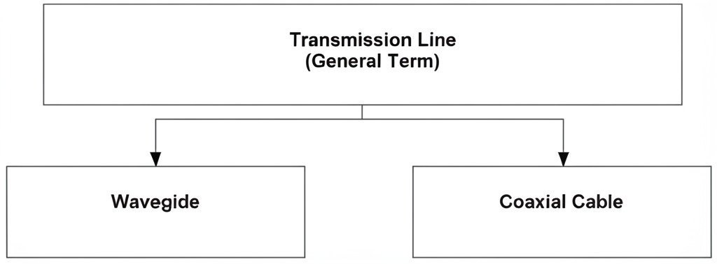
A transmission line is the general term for any structure designed to efficiently guide electromagnetic energy from one point to another. A waveguide is a specific type of transmission line, typically referring to a hollow conductive pipe, distinct from other types like coaxial cables or microstrip lines.
Dive Deeper into the Definitions
Understanding the hierarchy helps clear things up:
-
Transmission Line (General Category): The fundamental purpose is to transfer RF or microwave energy with minimal loss and reflection. Key characteristics of any transmission line include its characteristic impedance, propagation velocity, and attenuation (loss). The goal is usually to match the line’s impedance to the source and load impedances for maximum power transfer. Examples include:
- Coaxial Cable
- Waveguide (Hollow Pipe)
- Microstrip Line (Trace over ground plane on a PCB)
- Stripline (Trace embedded between two ground planes on a PCB)
- Parallel Wire Line (e.g., Twin-lead)
- Twisted Pair (Used mainly for lower frequencies/data)
-
Waveguide (Specific Type): This term usually refers to the hollow metal pipe structure we’ve discussed. It fits the definition of a transmission line because it guides electromagnetic waves. However, it operates on different principles (TE/TM modes, cutoff frequency) than TEM-mode lines like ideal coaxial cables.
-
Coaxial Cable (Another Specific Type): This is also a transmission line, but with a different physical structure and operating principle (primarily TEM mode) than a hollow waveguide.
So, all waveguides are transmission lines, but not all transmission lines are waveguides. Think of it like "vehicles" (transmission lines) and "trucks" (waveguides) versus "cars" (coaxial cables). They are both types of vehicles designed for transport, but they have different structures and are suited for different tasks. Our product lines cover multiple types of transmission line components, including various coaxial connectors, cable assemblies, adapters, and a wide range of waveguide products and accessories.
Conclusion
Choosing wisely matters: waveguides are ideal for high-frequency, high-power, low-loss fixed installations. Coaxial cables offer flexibility, broad bandwidth, and easier installation, especially suitable for lower frequencies and interconnects.
STAY IN FOR MORE NEWS
Subscribe to our free newsletter.

Basically, radar is used to collect the information related to the object or target like its range and location by radiating electromagnetic energy and examining the echo received from the distant object.
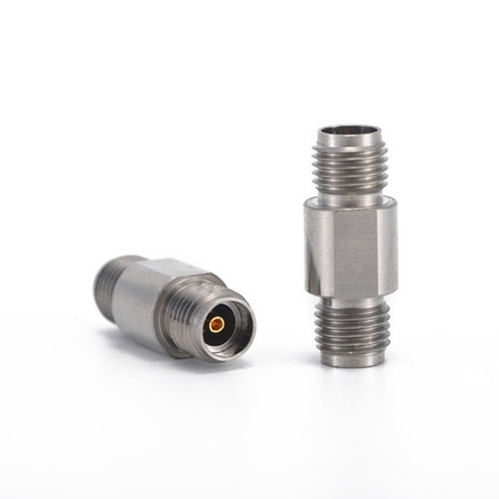
The 3.5mm adapter is an indispensable component for high-frequency 50-ohm RF systems, ensuring signal integrity and exceptional performance. Known for its precision and ability to operate at frequencies up to 34 GHz, this adapter is widely used across telecommunications, aerospace, and defense industries, where reliable RF connections are critical. Why Choose the 3.5mm Adapter? Seamless
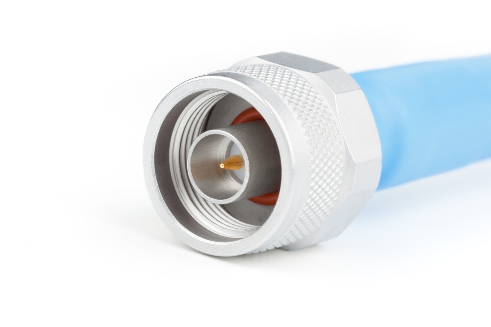
Did you know that the N-Type connector, a cornerstone of RF technology, has its roots in the 1940s? Originally designed for the U.S. Navy, this versatile connector has adapted to meet modern demands across telecommunications, defense, and high-frequency testing. The world of coaxial connectors has evolved into a vast array of types and standards, each
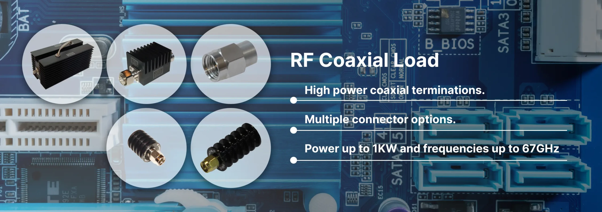
Discover Reach-Line’s precision RF and microwave terminations covering DC to 110 GHz and power levels 1 W to 1000 W. Reliable, low VSWR solutions for 5G, satellite, and lab applications.