by Angela
Share
")
Struggling with passive parts failing in high-power RF? Ignoring key specs can lead to costly burnout or poor signals. Understand these factors first to ensure reliability.
For high-power RF passives, focus on: power handling (average/peak), managing heat (thermal design), maintaining impedance match (low VSWR), operating within the correct frequency range, and ensuring environmental resilience. These prevent failure and ensure signal integrity.
These might seem like complex engineering points. But getting them wrong causes big headaches. Let’s break down why each one is so vital for your high-power systems, based on what we see day-to-day.
Why is Power Handling the Top Concern for These RF Devices?
Think you can just use any attenuator at high power? That assumption can literally fry your components. Proper power rating isn’t optional when dealing with serious wattage.
Exceeding power ratings causes overheating (thermal breakdown) and device failure. You must check both average power handling for continuous signals and peak power handling for pulsed signals to avoid burnout and ensure reliability.
Diving Deeper into Power Ratings
Power handling is often the first spec engineers look at for high-power passives, and for good reason. I remember early in my career [Placeholder for a story about underestimating power needs and causing a component failure] learning this lesson the hard way. Heat is the main enemy here. It’s generated primarily through resistive losses (I²R losses) in conductors and resistive elements, and dielectric losses in insulating materials, especially at higher frequencies. If a component can’t dissipate this heat faster than it’s generated, its temperature rises. Exceed the material’s limits, and you get thermal breakdown – the materials degrade, melt, or even burn out.
It’s crucial to distinguish between average power and peak power. Average power relates to the continuous thermal load. A device needs adequate heat sinking to handle this constantly generated heat. Peak power, common in pulsed systems like radar, relates to the maximum instantaneous voltage or current. Exceeding peak power limits might not immediately cause thermal failure but can lead to voltage breakdown (arcing) across gaps or through dielectrics, instantly destroying the device. Always check both specifications against your system requirements and include a safety margin (derating) – don’t operate right at the component’s maximum limit.
Diving Deeper into Impedance and Reflections
Impedance matching is fundamental in all RF, but the consequences of getting it wrong are amplified at high power. We often troubleshoot systems [Placeholder for a story about diagnosing high VSWR causing amplifier issues] where mismatch is the root cause. When an RF signal traveling down a transmission line (like a cable or inside a component) encounters a change in impedance, part of the signal reflects back towards the source. This creates standing waves, measured by the Voltage Standing Wave Ratio (VSWR). A perfect match is 1:1 (no reflection), while higher values indicate increasing mismatch.
Why is this bad? First, reflected power is power not delivered to the intended load (like an antenna or the next stage). This means inefficiency. Second, the reflected power travels back to the source. High-power amplifiers are often sensitive to reflected power – it can cause them to oscillate, reduce their output, distort the signal, or even suffer permanent damage. Consistent impedance (usually 50 ohms in RF/microwave systems) across all components – cables, connectors, attenuators, splitters – is critical. Even a poorly installed connector can introduce significant mismatch.
What Are the Real Risks if You Neglect Heat in High-Power RF?
Components feeling hot isn’t just a minor inconvenience in high-power systems. Ignoring thermal management drastically shortens device life and can lead to sudden, complete system failure when you least expect it.
Neglecting heat leads to component overheating. This causes performance drift (parameters change), reduced reliability, shortened lifespan, and potentially catastrophic failure. Effective heat sinks, cooling systems, and material choices are essential.
Beyond Power and Heat, Why Worry About Frequency and Environment?
Picked a part rated for the power and it seems okay thermally, but it still fails or performs poorly? The operating frequency and the surrounding environment play bigger roles than many initially realize.
Components perform optimally only within their specified frequency range; outside this, loss increases and mismatch worsens. Environmental factors like extreme temperatures, vibration, and moisture can also degrade performance or cause physical failure if not accounted for.
Diving Deeper into Frequency and Environmental Effects
I worked on a project using components near their upper frequency limit [Placeholder for a story about unexpected performance issues due to frequency limits or environment], and we saw firsthand how performance can drop off. RF passive components aren’t perfect broadband devices. Their key parameters, like insertion loss and VSWR, are frequency-dependent. Manufacturers specify an operating frequency range where the device meets its specifications. Operating outside this range often results in significantly higher loss and poorer impedance match, degrading system performance. Always ensure your operating frequency falls comfortably within the component’s specified range.
Environmental factors are just as critical, especially for systems deployed outside the lab.
- Temperature: Extreme hot or cold can cause materials to expand or contract, potentially stressing connections or changing electrical properties. Performance parameters often drift with temperature.
- Vibration and Shock: Common in aerospace, automotive, or mobile applications, mechanical stress can loosen connectors, crack solder joints, or damage delicate internal structures.
- Moisture and Humidity: Can lead to corrosion on connectors and internal parts, degrading electrical contact. Moisture ingress can also change the dielectric properties of materials, affecting impedance and loss, or even cause short circuits.
Consideration of these factors leads to choosing appropriately ruggedized components, perhaps with specific environmental ratings (like IP ratings for sealing against dust/water) or adherence to military standards (MIL-STD) for temperature, shock, and vibration resistance.
Conclusion
Choosing high-power RF passives means carefully checking power handling (peak/avg), ensuring good impedance matching, managing heat effectively, respecting frequency limits, and considering environmental stresses. Getting these right is key to reliable system performance.
STAY IN FOR MORE NEWS
Subscribe to our free newsletter.

Introduction RF connectors are essential components used in communication systems to transmit high-frequency signals. Among the many types of RF connectors available, SMA connectors and N type connectors are two of the most widely used. Both connectors are designed for coaxial cable connections, but they differ significantly in size, frequency performance, power handling capability, and
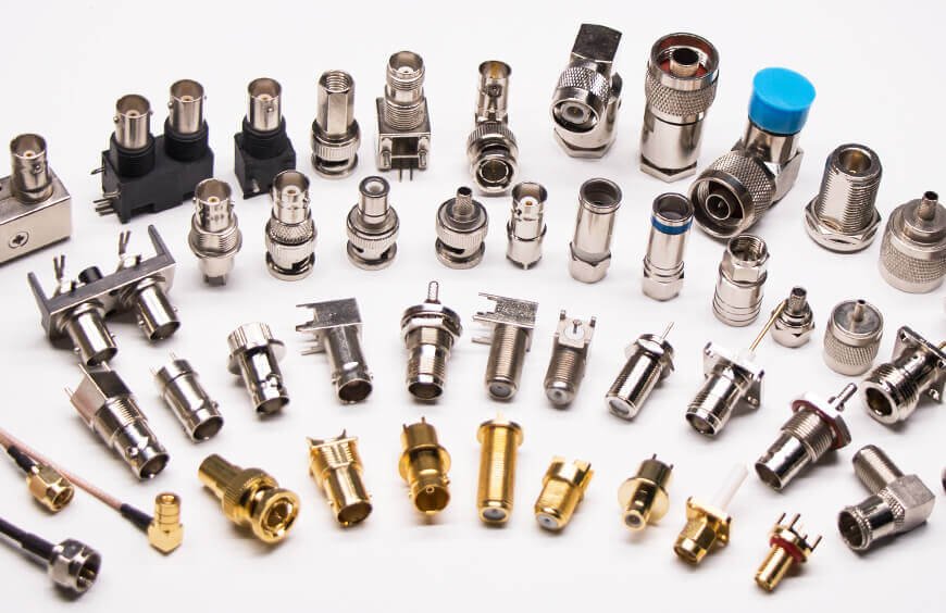
Introduction RF connectors are essential components in modern communication and electronic systems. They are designed to connect coaxial cables to various RF devices while maintaining signal integrity and minimizing signal loss. From wireless communication and satellite systems to test equipment and radar technology, RF connectors play a critical role in ensuring reliable transmission of high-frequency
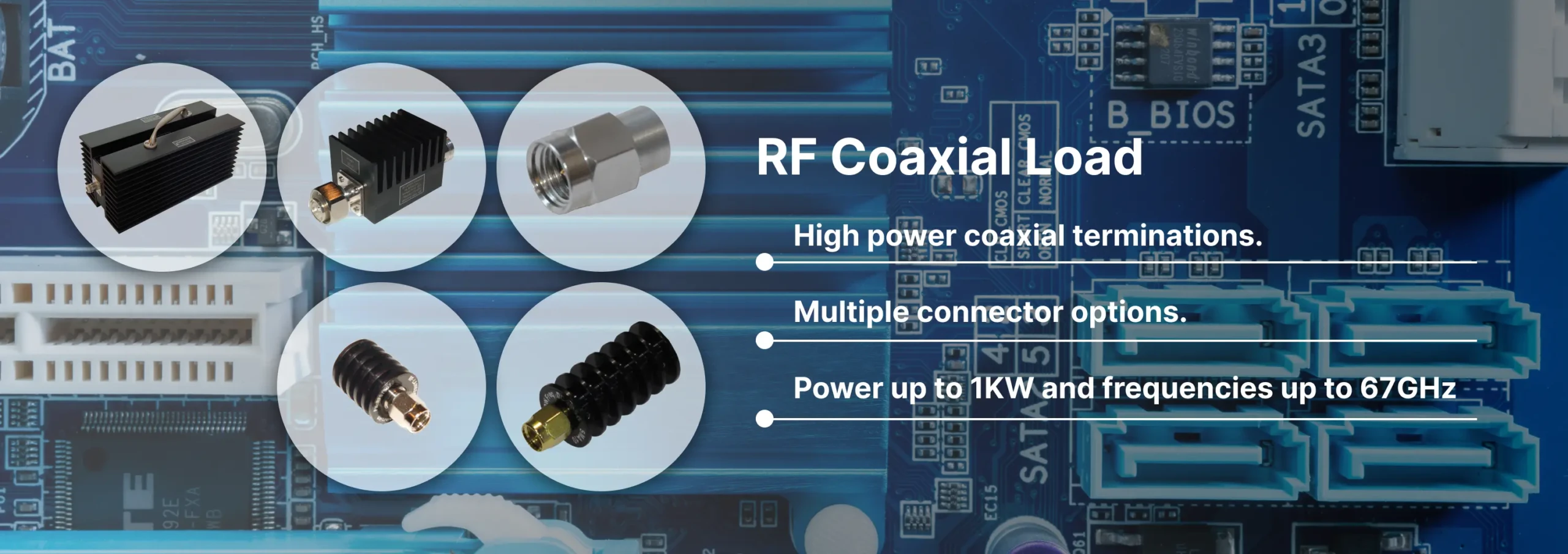
Discover Reach-Line’s precision RF and microwave terminations covering DC to 110 GHz and power levels 1 W to 1000 W. Reliable, low VSWR solutions for 5G, satellite, and lab applications.
Reach-Line offers high-frequency cable assemblies, fixed attenuators, and precision terminations. Partner for engineering support, rapid prototyping, and global logistics.