
by Angela
Share
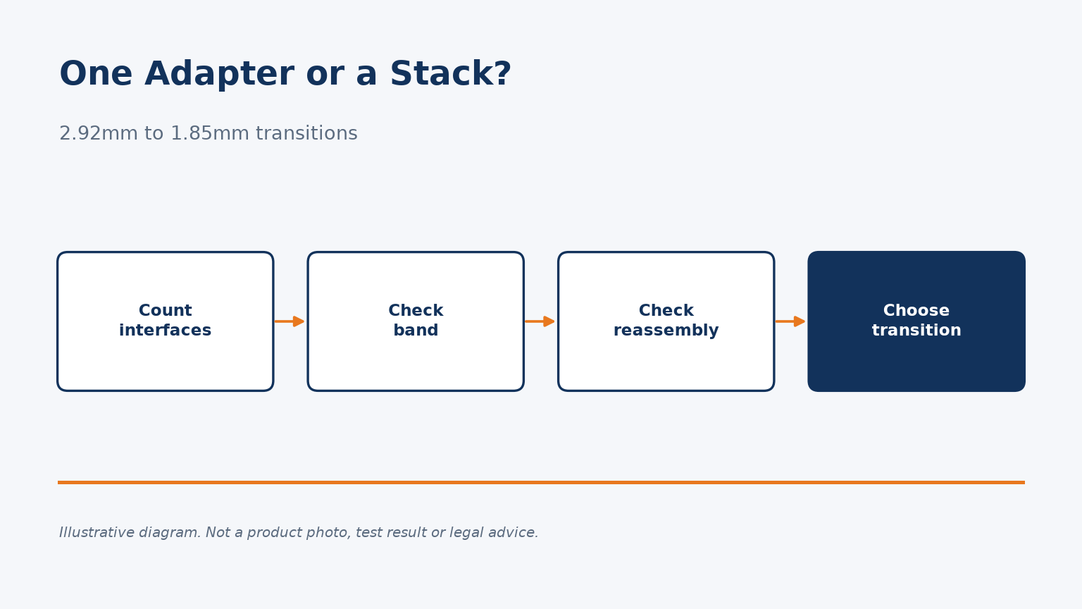
Stacked adapters get a 2.92mm port onto a 1.85mm device quickly. They also add loss, ripple and measurement spread.
Use a single 2.92mm to 1.85mm adapter whenever the path is reassembled often, measured near a limit, or used at high frequency. A stack is acceptable only for quick checks with large margins or when calibrated in and left assembled.
Below I compare the two in detail; if you want to replace a stack now, tell us your ports and band.
What is an adapter stack, and why do engineers end up with one?
When the right part is not on the shelf, two or three adapters screwed together seem to solve the problem in minutes.
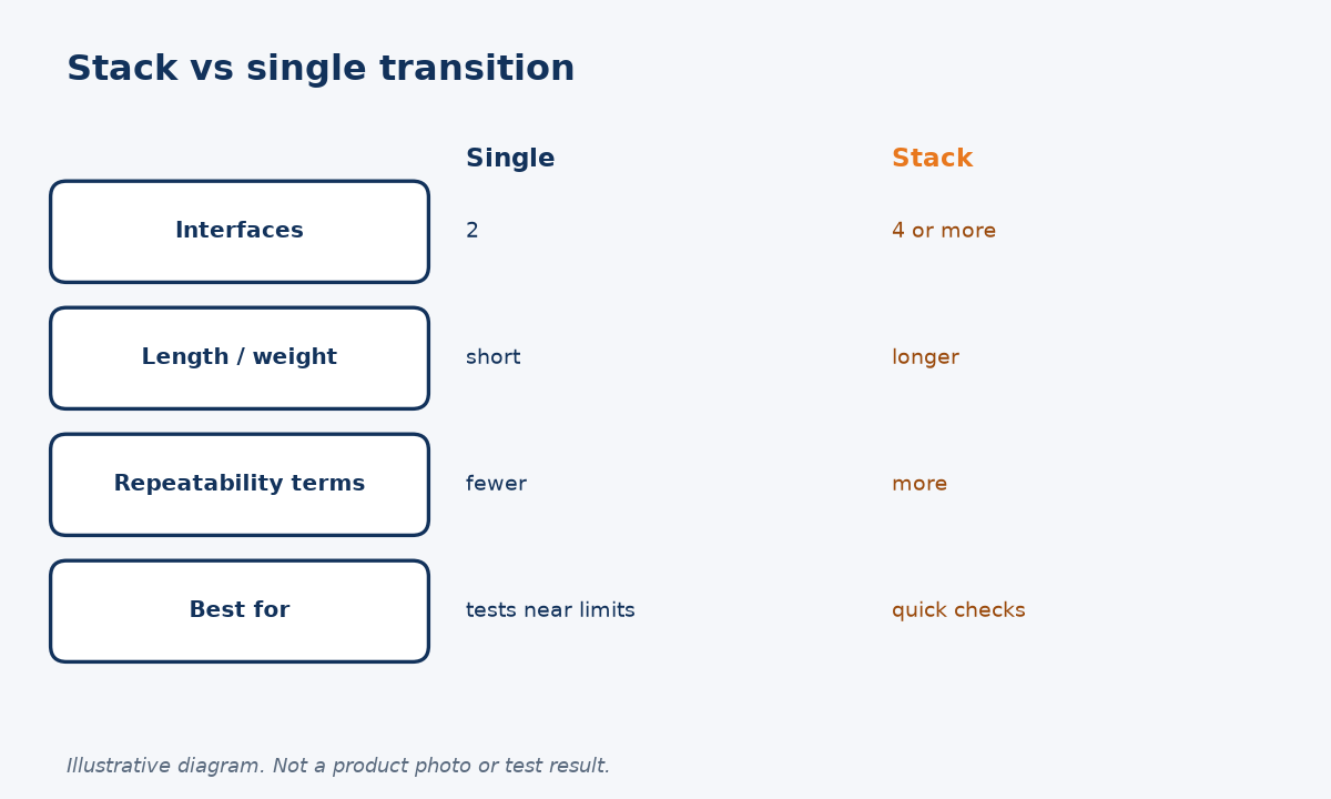
An adapter stack chains several adapters to get from one connector series to another, for example 2.92mm to an intermediate series and then to 1.85mm. It works, but every added interface adds reflection, loss, length and a new repeatability term.
Convenience now, uncertainty later
Stacks appear because labs keep drawers of common adapters but rarely the exact transition a new test needs. Moving from a 2.92mm port to a 1.85mm device is a typical case: the interfaces are different series defined in MIL-STD-348, and a single direct adapter may not be in stock.
Each interface in a stack is a small discontinuity. Individually it may be well within specification; together they add up, and their reflections can combine in ways that create ripple across frequency. The stack is also physically longer and heavier, which puts more bending moment on the instrument port.
There is a measurement issue too. NIST work on coaxial connectors (Lewandowski and Williams) identifies connector repeatability as the primary source of random error in coaxial S-parameter and power measurements. A stack has more connections that can vary each time it is assembled. I view a stack as an acceptable short-term fix for a quick check, and a poor choice for a production test or a calibrated setup. A single transition, such as our 2.92mm male to 1.85mm female adapter (RL-2.92/1.85-JKG), replaces two or more of those connections.
How much can a stack cost you in loss and match?
The penalty of a stack is easy to underestimate because each adapter's datasheet looks fine on its own.
Insertion losses add roughly in dB, while reflections from several interfaces can add in phase at some frequencies and cancel at others. The worst-case match of a stack is therefore poorer than any single adapter, and it varies with frequency.
An illustrative comparison
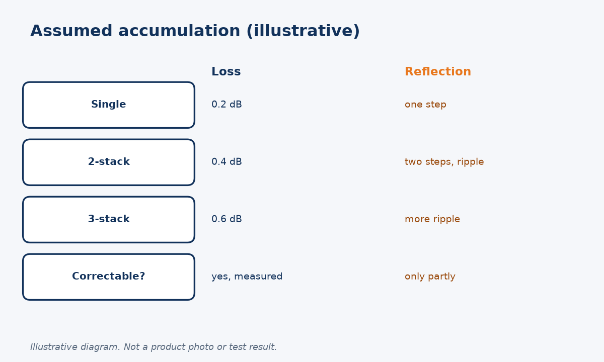
The table uses assumed values to show the shape of the trade-off; they are not Reach Line data and real figures depend on the parts and band.
| Configuration | Interfaces in path | Assumed loss each | Total (assumed) |
|---|---|---|---|
| Single transition | 2 | 0.2 dB | 0.2 dB |
| Two-adapter stack | 4 | 0.2 dB per adapter | 0.4 dB |
| Three-adapter stack | 6 | 0.2 dB per adapter | 0.6 dB |
Loss is usually the smaller worry, because it can be measured and corrected. Reflection is harder. When two discontinuities sit a short distance apart, their reflections combine with a phase that changes with frequency, so the overall return loss can show peaks and dips that neither adapter shows alone. In a test setup this appears as ripple that is easy to mistake for a property of the device under test.
I would also note the frequency ceiling: a chain is only rated as high as its lowest-rated element. Our RL-2.92/1.85-JKG listing gives DC to 40 GHz, so it suits paths up to that limit. If your measurement band is different, tell us the band and we will suggest the right transition.
When is a stack still acceptable?
Not every stack is a mistake. The question is whether the extra uncertainty matters for the result you need.
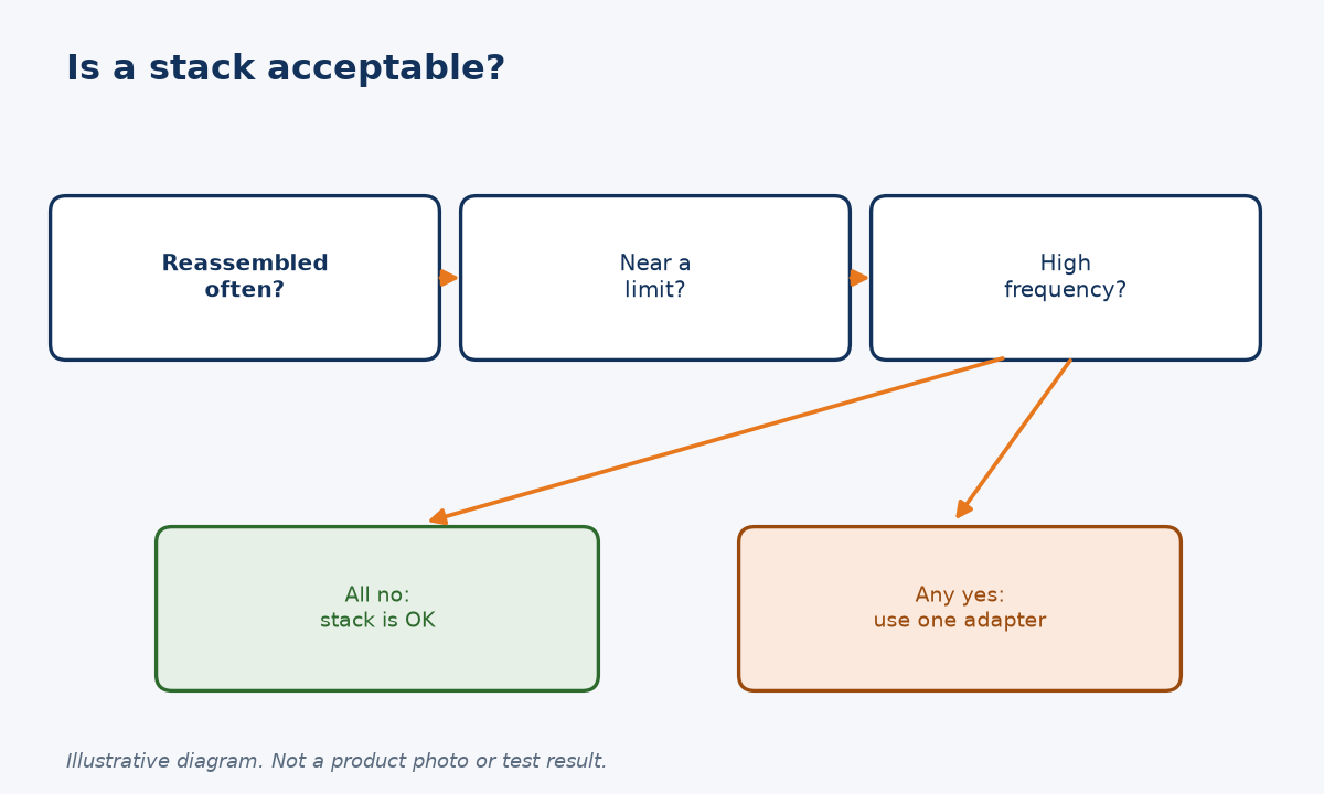
A stack is acceptable for low-frequency checks, quick functional tests with large margins, or when the stack is included inside a calibration and never disassembled. It is a poor choice when it is reassembled often or used near specification limits.
Calibrate it in, or replace it
If a stack is assembled once and then included inside a vector network analyser calibration, the calibration removes much of its systematic effect. What remains is the random part: the variation each time a connection is broken and remade. NIST work by Koepke and Jargon identifies disconnect and reconnect as one of the components of variance in repeated S-parameter measurements, so a stack that stays assembled behaves much better than one that is taken apart daily.
The opposite case is a production fixture where operators build and rebuild the stack, or a measurement whose result is close to its limit. Here, every extra connection widens the spread of results, and you may end up retesting good parts or arguing with a supplier over readings.
My rule of thumb is simple: if the path crosses a test limit that matters commercially, or is assembled more than occasionally, replace the stack with a single transition. If it is a one-off sanity check far from any limit, a stack is fine. Either way, write down the configuration so results can be reproduced.
What should you specify when ordering a transition adapter?
A direct transition adapter is a small part, but getting the order right avoids a second round of samples.
Specify both interface series and genders, the frequency band, the maximum VSWR or return loss across it, insertion loss if it matters, body material, quantity, and whether you need per-unit test data. Check the gender direction against your ports.
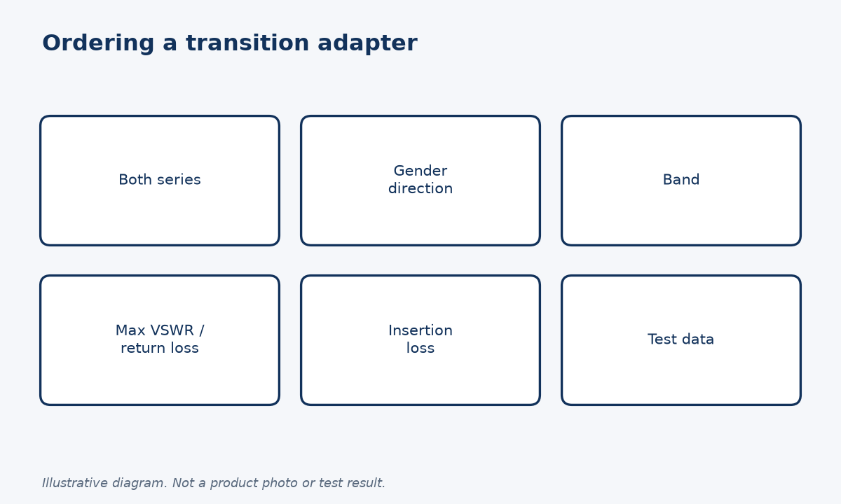
Gender direction causes most wrong orders
The most common ordering error with transitions is gender direction: 2.92mm male to 1.85mm female is a different part from 2.92mm female to 1.85mm male. Write the configuration as seen from your instrument port, and if possible attach a sketch. Name the series with reference to MIL-STD-348 so there is no doubt about the interface.
For the electrical lines, state the band you will actually use and a reflection limit across it. If the adapter will sit in a calibrated path, the match matters more than the loss; if it is in a power-budget path, loss matters too. Our RL-2.92/1.85-JKG listing gives 50 ohms, DC to 40 GHz, a passivated stainless steel body, gold-plated beryllium-copper contacts, PEI insulator, -55 °C to +85 °C and at least 500 matings.
For background on how 2.92mm relates to other series, see our 2.92mm vs 3.5mm vs SMA compatibility guide. To replace a stack in your setup, send us the port types and band, or go straight to the 2.92mm to 1.85mm adapter page and request a quote.
Conclusion
If the path matters, count the interfaces and replace the stack with one transition adapter.
STAY IN FOR MORE NEWS
Subscribe to our free newsletter.
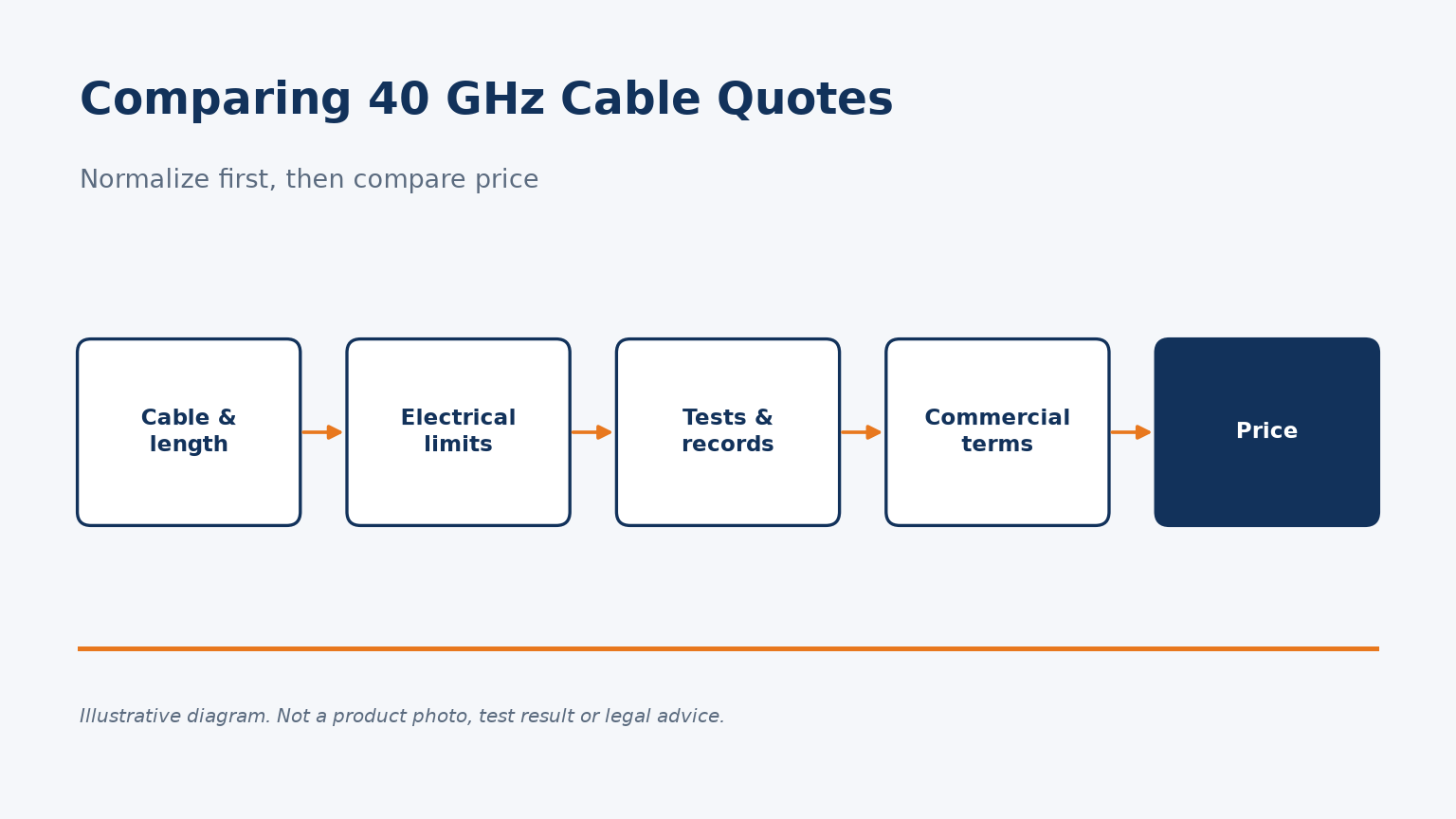
How to compare 2.92mm 40 GHz cable assembly quotes fairly: normalize cable, length, guaranteed limits, test records and commercial terms.
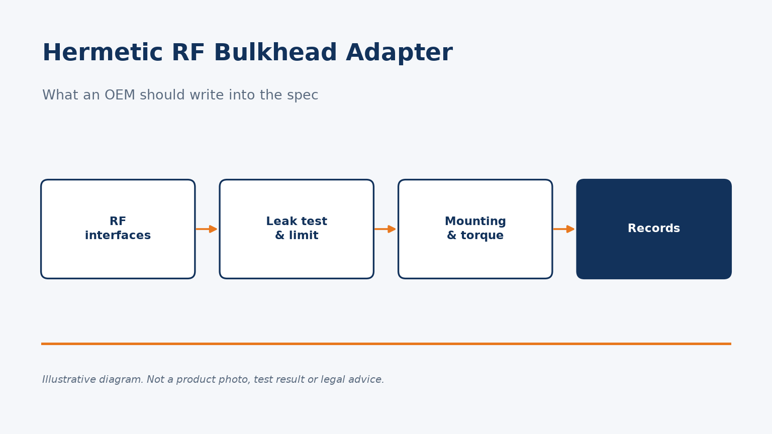
What OEM buyers should specify for a hermetically sealed RF bulkhead adapter: leak-test method and limit, mounting, torques and records.
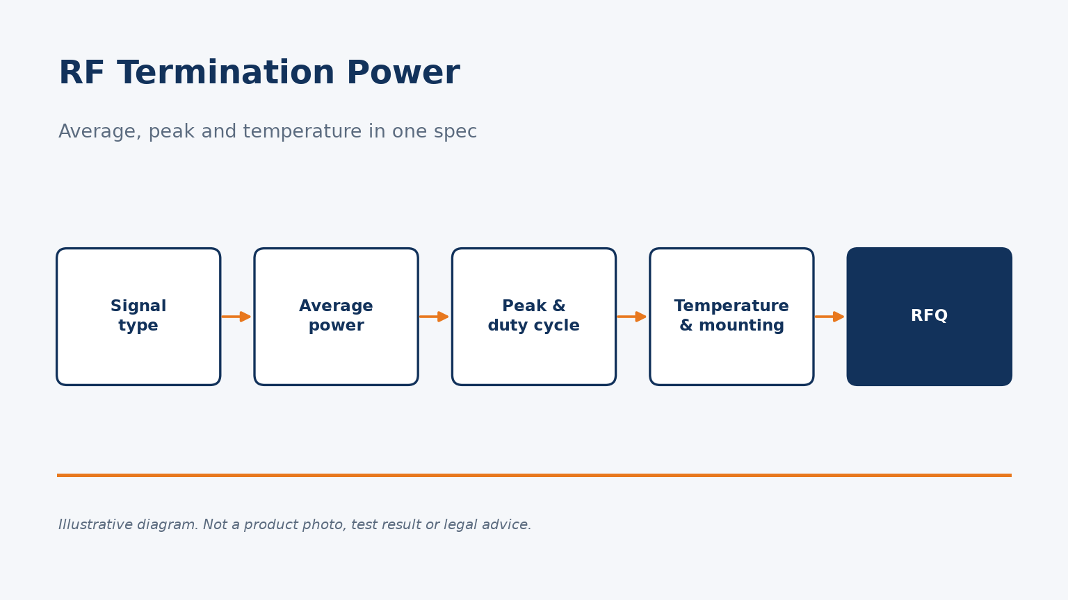
How to specify RF termination power for CW and pulsed signals: average vs peak, duty cycle, temperature derating, and an RFQ checklist.
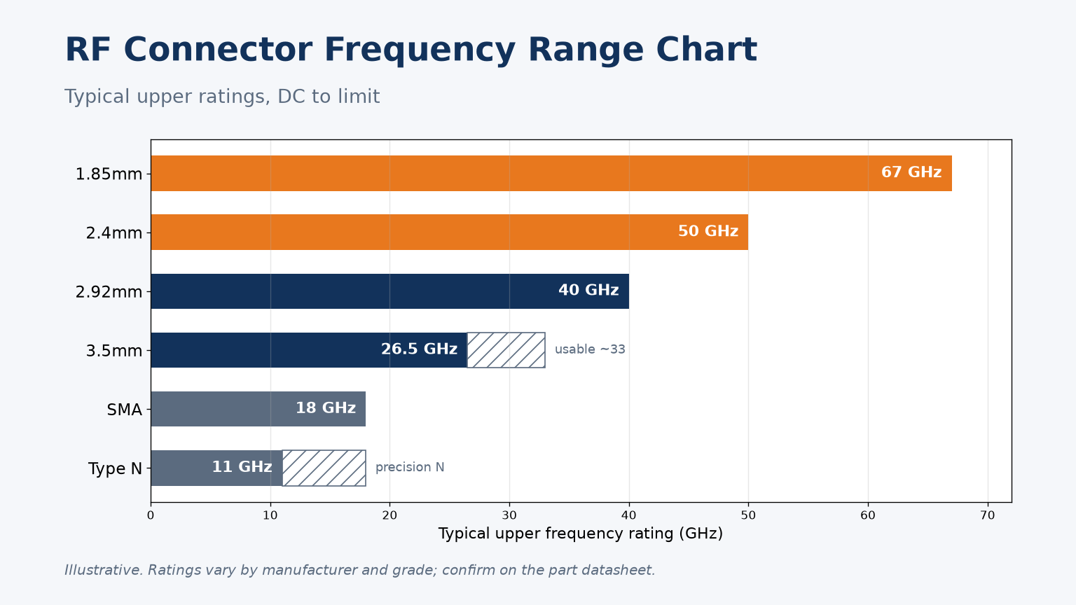
Frequency range chart for Type N, SMA, 3.5mm, 2.92mm, 2.4mm and 1.85mm connectors, why the limits exist, which ones mate, and how to specify a path.
