by Angela
Share
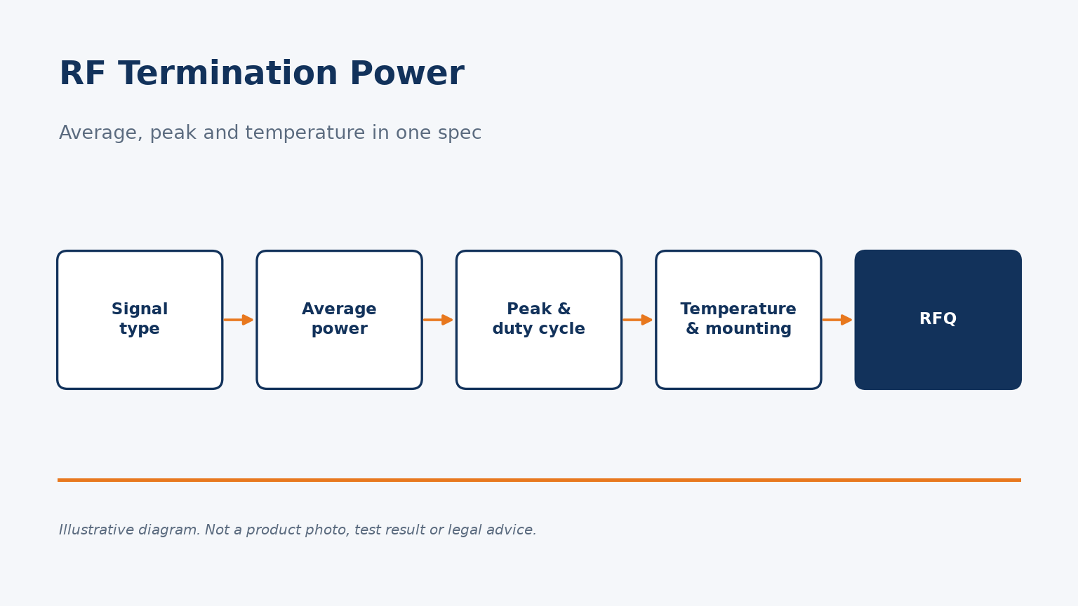
Terminations fail quietly when the power rating on the order does not match the signal they actually absorb.
Specify an RF termination by average power at your worst-case temperature, plus peak power, pulse width and duty cycle for pulsed signals, together with interface, impedance, frequency band and return loss. A bare watt figure is not a specification.
Below I explain each item; if you already know your signal, you can send it to us for a termination recommendation.
Why is a single watt figure not enough to specify an RF termination?
A purchase order that says "2 W termination" leaves three questions open: 2 W of what, at what temperature, and for how long.
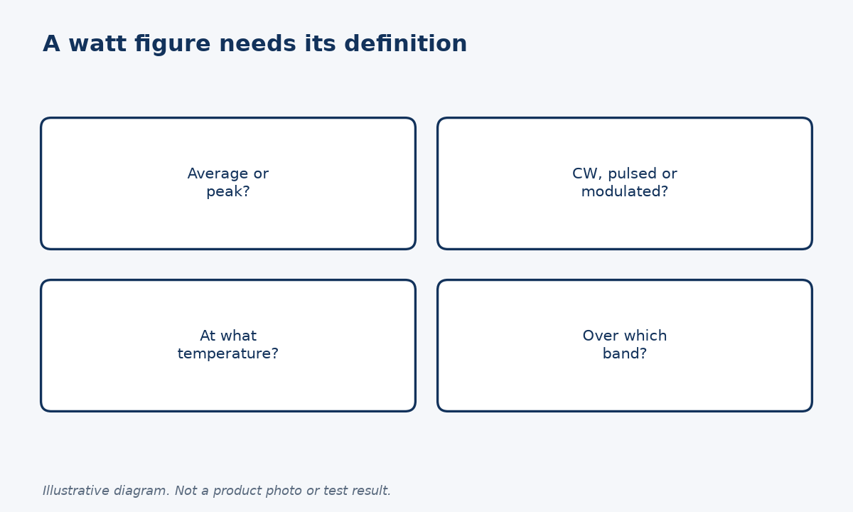
A watt rating only means something with its definition. State whether it is average or peak power, the signal type (CW, pulsed or modulated), the ambient or heat-sink temperature, and the frequency band. Without these, two suppliers can quote the same number for different capabilities.
What the number usually describes
In RF metrology the default meaning of power is average power. The National Bureau of Standards survey of RF power measurement, NBS Circular 536, defines P as the average power over one cycle, and for complex wave shapes over a longer interval, and treats peak-reading instruments as a separate class. A termination datasheet that gives one watt value without saying which kind is therefore most likely describing average power, but you should not have to guess.
A termination turns RF energy into heat. Its average rating is really a thermal limit: how much heat the resistive element and body can carry away at a stated temperature. A peak limit is a different failure mechanism, related to voltage stress and short-term heating of the element. One number cannot describe both.
My view is that buyers should treat an unqualified watt figure as incomplete rather than wrong. Ask the supplier to confirm the definition before you approve a part. For example, our 2.92mm male termination (P/N RLTS2J40) is listed at 2 W; if your signal is pulsed, send us the waveform and we will confirm whether that rating fits.
How do you convert a pulsed signal into the numbers a supplier needs?
Pulsed and bursty signals are where most termination specifications go wrong. The average can be small while the peaks are very large.
For a repetitive rectangular pulse, average power equals peak power times duty cycle, where duty cycle is pulse width divided by the pulse period. Give the supplier peak power, pulse width and repetition rate, not only the average, so they can check both limits.
A worked example with assumed values
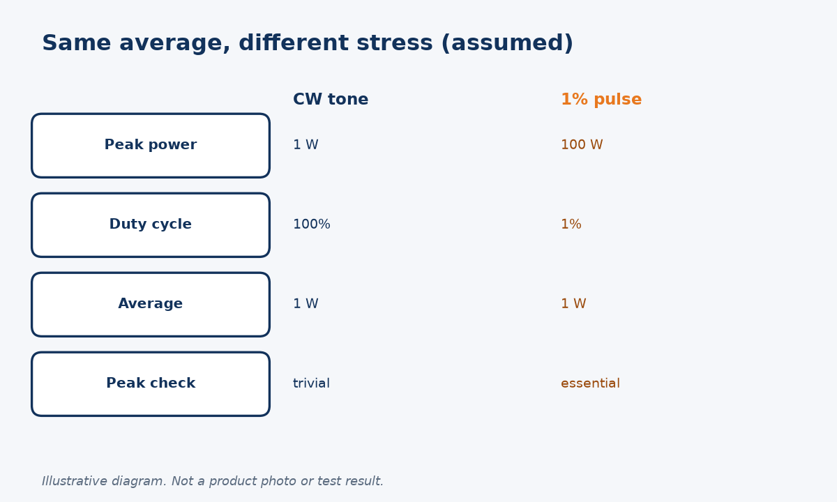
The relationship itself is simple arithmetic. If a pulse is on for a fraction D of each period, average power is the peak power multiplied by D. The table uses assumed numbers to show why both values matter; they are illustrations, not Reach Line ratings.
| Assumed signal | Peak power | Duty cycle | Average power |
|---|---|---|---|
| CW test tone | 1 W | 100% | 1 W |
| Radar-like pulse | 100 W | 1% | 1 W |
| Burst test | 20 W | 10% | 2 W |
All three rows have a similar average, so a thermal rating alone would accept them all. The second row, however, applies one hundred times more instantaneous power than the first. Whether a given termination survives it depends on its peak limit, which may not be published.
Two cautions apply. First, the formula assumes rectangular pulses with a constant duty cycle; modulated signals with a high peak-to-average ratio need their peak envelope stated directly. Second, as Circular 536 makes clear, average-reading and peak-reading instruments measure different things, so state which one produced your numbers. If you are unsure how to describe your waveform, send it to our engineers and we will help you turn it into a termination specification.
How do temperature and mounting change the usable power?
A rating measured on an open bench at room temperature may not hold inside a hot enclosure.
Average power ratings are tied to a reference temperature and a way of removing heat. Tell the supplier your maximum ambient or chassis temperature, airflow, and whether the termination is mounted to a heat sink, so they can apply any derating needed.
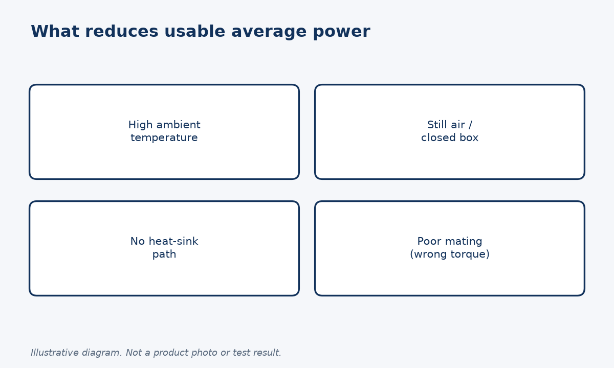
Ask for the derating basis
Because the average rating is a heat limit, anything that makes heat harder to remove reduces the usable power. Higher ambient temperature, still air, a closed box or a plastic panel all push in the same direction. Suppliers typically publish a rating at a reference temperature and may provide a derating curve above it; if they do not, ask for one or ask for the rating at your worst-case temperature.
Operating temperature range is a separate figure from power rating. Our RLTS2J40 listing, for example, gives a temperature range of -55 °C to +85 °C. That tells you where the part can operate, not how much power it can absorb at the top of that range. I would ask for both numbers, and for the power figure to be stated at your actual worst-case temperature.
Connector handling matters too. NASA's workmanship standard NASA-STD-8739.4A says coaxial mating torque should come from engineering documentation, with only the coupling nut turned. A poorly mated interface adds contact resistance and local heating, which is the last thing a termination running near its limit needs. Interfaces themselves are defined in MIL-STD-348, so naming the series and gender removes doubt about fit.
What should an RF termination RFQ include?
Turning the points above into a short checklist makes quotes comparable and avoids returns.
Include interface series and gender, impedance, frequency band, return loss or VSWR limit, average power at your worst-case temperature, peak power with pulse width and duty cycle, quantity and any test data you need with each unit.
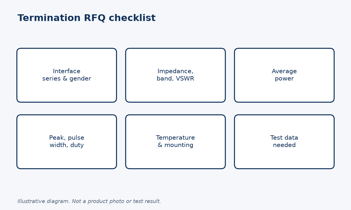
A checklist you can paste into an RFQ
I suggest grouping the request into four lines: electrical, power, environment and records. Electrical covers impedance, band and the reflection limit you need across that band. Power covers average power, peak power and the pulse description. Environment covers temperature, airflow and mounting. Records cover whether you want typical data or per-unit test plots.
A frequent mistake is to specify only the connector type and wattage, because terminations look like simple parts. Yet the reflection limit across your band often matters as much as power, especially when the termination sits on a test port or a coupler and its match affects the measurement. Our earlier article on high-frequency terminations covers the general product family; this checklist is about getting the power question right.
| RFQ line | What to state |
|---|---|
| Interface | Series, gender (e.g. 2.92 mm male) |
| Electrical | Impedance, band, VSWR or return loss |
| Power | Average, peak, pulse width, duty cycle |
| Environment | Max temperature, airflow, mounting |
When the list is ready, request a quote or open the RLTS2J40 product page to check the listed data. Please confirm the frequency range with us before ordering, as we will quote against your band.
Conclusion
Write average power at worst-case temperature and peak power with duty cycle; then any supplier can check your termination fits.
STAY IN FOR MORE NEWS
Subscribe to our free newsletter.
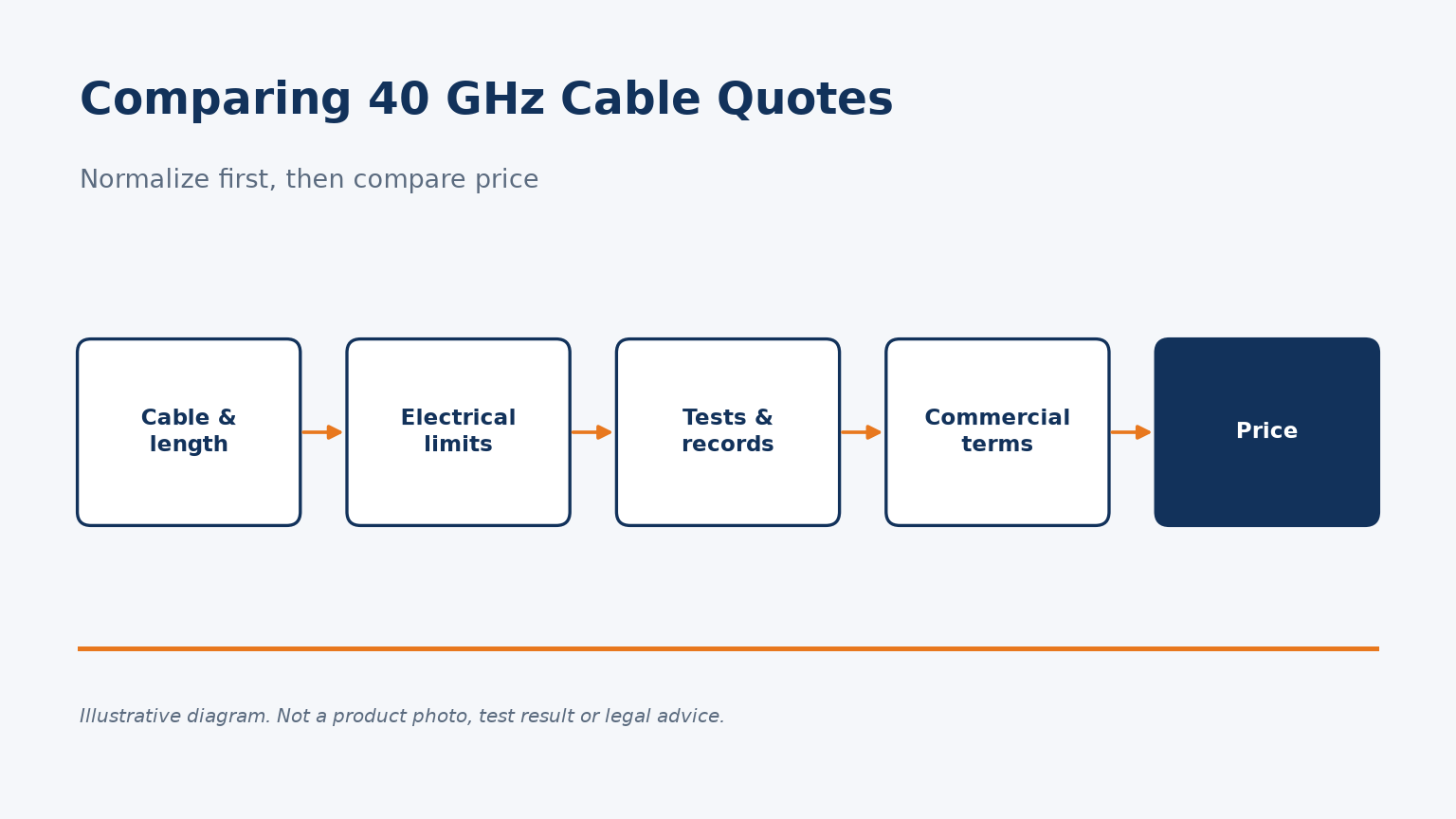
How to compare 2.92mm 40 GHz cable assembly quotes fairly: normalize cable, length, guaranteed limits, test records and commercial terms.
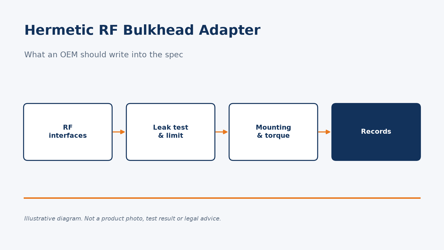
What OEM buyers should specify for a hermetically sealed RF bulkhead adapter: leak-test method and limit, mounting, torques and records.
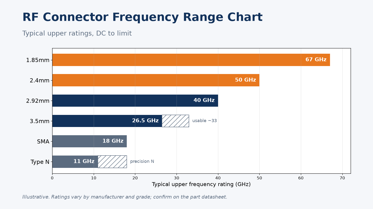
Frequency range chart for Type N, SMA, 3.5mm, 2.92mm, 2.4mm and 1.85mm connectors, why the limits exist, which ones mate, and how to specify a path.
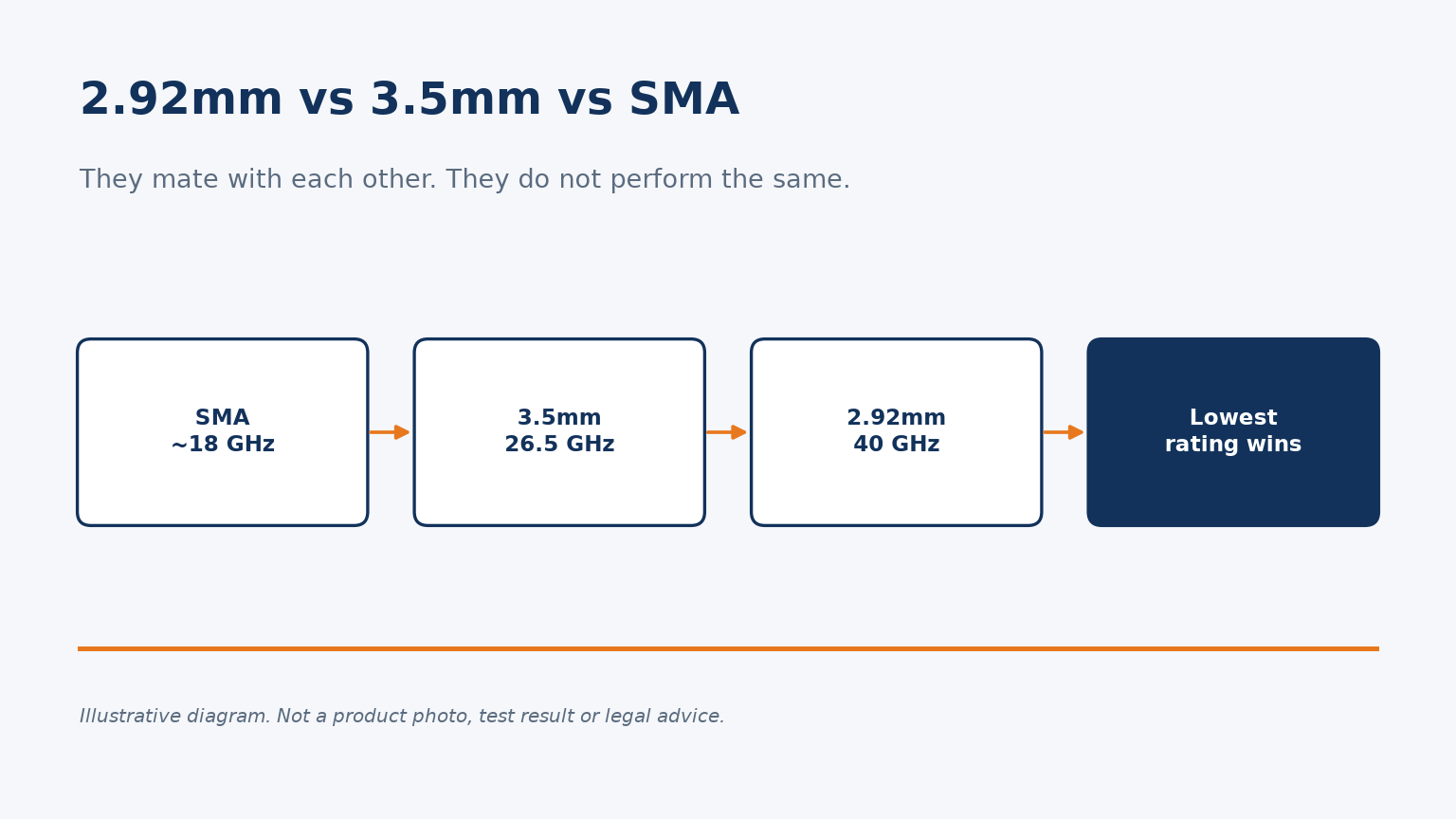
SMA, 3.5mm and 2.92mm connectors intermate, but not at the same frequency. Ratings, mixing rules, torque and when to choose each one.
