by Angela
Share

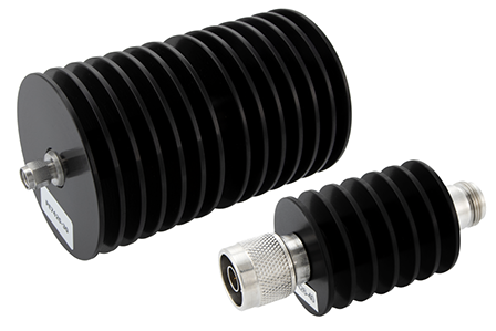
RF attenuators are essential components in many RF and microwave systems, designed to reduce the power of a signal without significantly affecting its integrity. Whether in test equipment, communication systems, or for signal protection, RF attenuators play a key role in ensuring optimal system performance. In this article, we will explore what an RF attenuator is, how it works, its types, applications, and how to choose the right one.
What Is an RF Attenuator?
An RF attenuator is a passive electronic device used to reduce the amplitude or power of a radio frequency signal. Unlike amplifiers, which boost signal strength, RF attenuators lower the signal’s power in a controlled manner. They are critical in preventing signal overloads in systems like spectrum analyzers and RF communication systems.
Key characteristics of RF attenuators include:
-
Attenuation value (measured in decibels, dB)
-
Frequency range
-
Power handling capacity
-
Impedance (typically 50 ohms)
RF attenuators help ensure that signals maintain the correct power level for sensitive devices, preventing potential damage or distortion.
How Do RF Attenuators Work?
RF attenuators work by using resistive networks (often composed of resistors) to dissipate part of the signal’s energy as heat, reducing its power. These resistors are carefully designed to maintain impedance matching throughout the signal path to avoid reflections that could cause signal distortion.
There are different circuit configurations for RF attenuators, including:
-
Pi (π) network
-
T network
-
Bridged-T network
In all these designs, the attenuator ensures that only a portion of the signal’s energy is absorbed, while the remaining signal passes through at a reduced level, maintaining the desired power attenuation.
Types of RF Attenuators
There are three main types of RF attenuators, each serving different purposes in various applications.
Fixed Attenuators
A fixed attenuator provides a constant attenuation value, which cannot be adjusted. Common values are 3 dB, 6 dB, and 10 dB. Fixed attenuators are ideal when you need a consistent reduction in signal power.
Variable Attenuators
Variable attenuators allow manual adjustment of the attenuation level. They are often used in RF testing and signal calibration, where the ability to fine-tune signal strength is required.
Programmable Attenuators
A programmable attenuator provides electronic control of attenuation levels. It is commonly used in automated test systems and advanced RF applications where precise and remote control of signal power is necessary.
Applications of RF Attenuators
RF attenuators are used in a variety of industries and applications, including:
Test Equipment
Attenuators are widely used in RF testing equipment, such as vector network analyzers and signal generators, to reduce the signal power and protect sensitive devices from high power levels. They ensure that signals are within the measurement range of the equipment, enabling accurate testing.
Communication Systems
In wireless communication systems, RF attenuators are used to manage signal power between transmitters and receivers. For example, in cellular networks and satellite communication systems, they help ensure proper signal levels are maintained for optimal communication quality.
Signal Protection
RF attenuators protect sensitive devices, such as RF receivers and measurement equipment, from excessive signal power. They are crucial when dealing with high-power signals or when connecting different RF systems that may have mismatched signal levels.
How to Choose an RF Attenuator
Selecting the right RF attenuator depends on several factors:
1. Frequency Range
Make sure the attenuator covers the frequency range of your application. RF attenuators are available for a wide range of frequencies, from DC to several GHz or even millimeter-wave frequencies.
2. Attenuation Value
Choose an attenuator with the appropriate attenuation value based on your requirements. Typical values include 3 dB, 6 dB, 10 dB, and 20 dB.
3. Power Rating
Check the maximum power handling of the attenuator to ensure it can safely handle the input signal without causing damage.
4. Connector Type
RF attenuators come with various connector types, including SMA, N-type, 2.92mm, and 2.4mm. Choose the one that matches your system’s connectors.
5. VSWR Performance
The VSWR (Voltage Standing Wave Ratio) should be low to ensure minimal signal reflection and maximum power transfer.
Learn more about our RF products here. https://reach-line.com/product-category/precision-rf-microwave-mmwave-fixed-attenuators/
Conclusion
An RF attenuator is a critical component for controlling signal power in RF and microwave systems. Whether used in test equipment, communication systems, or signal protection, RF attenuators help maintain system stability, ensure accurate measurements, and protect sensitive devices from signal overload.
When selecting an RF attenuator, consider key factors such as frequency range, attenuation value, power handling, connector type, and VSWR performance. By understanding how RF attenuators work and their various types, you can choose the right one for your specific application, ensuring optimal performance and reliability in your RF systems.
STAY IN FOR MORE NEWS
Subscribe to our free newsletter.

If you are a newcomer in the RF industry, it must be difficult to distinguish VSWR and return loss. The following is a comparison table of VSWR and return loss.
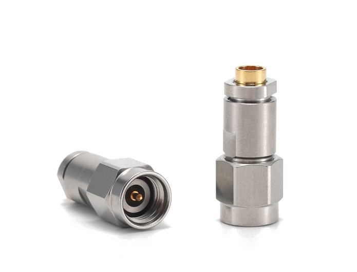
With options like SMA, N-Type, and 2.92mm available, picking the right one feels complex and mistakes can be costly. SMA is common up to 18 GHz, N-Type is larger and robust for power/outdoor use up to 11-18 GHz, while 2.92mm offers precision performance up to 40 GHz and is mechanically compatible with SMA. Selecting the
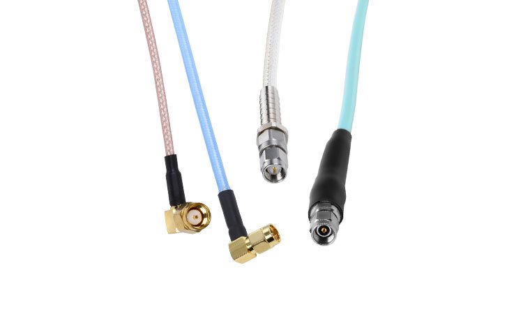
SMA connectors/adapters and cable assemblies are crucial components widely used in RF testing and measurement applications. These connectors are known for their miniature size, wide frequency range, and excellent electrical performance.

RF, microwave, and millimeter-wave describe frequency ranges with distinct uses. RF covers 3 kHz to 300 GHz, including microwaves and mmWave. Microwaves occupy 300 MHz to 300 GHz, while mmWave strictly focuses on 30 GHz to 300 GHz. Each handles specific tech needs.