by Angela
Share
Need components with low VSWR? Browse our precision adapters, cable assemblies and terminations.
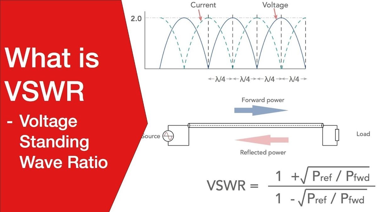
Voltage Standing Wave Ratio (VSWR) is a critical parameter in RF (Radio Frequency) systems, indicating how effectively power is transferred from a source to a load. It measures the ratio of the maximum to the minimum voltage in a standing wave formed by reflected and transmitted signals.
What Is VSWR?
VSWR is calculated by comparing the impedance of the transmission line (or antenna) to the impedance of the load. A low VSWR indicates that most of the power is being transmitted, while a high VSWR suggests significant reflection, resulting in energy loss and potential damage to the RF system.
Why Is VSWR Important?
Efficiency: A low VSWR ensures minimal reflection, maximizing energy transfer and reducing signal loss.
System Protection: High VSWR can cause reflected power to return to the source, potentially damaging components like transmitters and amplifiers.
Signal Quality: High VSWR can distort signals, affecting communication systems, particularly in critical applications like satellite communication, wireless networks, and radar systems.
How to Improve VSWR
Use of Proper Impedance Matching: Matching the impedance of all RF components (e.g., cables, connectors, antennas) ensures minimal reflection.
Quality Components: High-quality RF components, such as adapters, attenuators, and terminations, can help reduce VSWR by minimizing mismatches.
Regular Testing: Continuous monitoring with VSWR meters helps identify and address issues before they impact system performance.
VSWR in Real-World Applications
In telecommunications, aerospace, and military systems, maintaining a low VSWR is essential for high-performance communication and preventing system downtime. Using precise RF components such as low-loss coaxial cables and accurate terminations ensures that power is efficiently transmitted without reflections.
Effects of High VSWR on RF Systems
A high VSWR can have several detrimental effects on the performance and longevity of RF systems:
- Signal Reflection: When there is a mismatch in impedance, a portion of the signal is reflected back towards the source. This results in interference that can degrade the quality of the transmitted signal, leading to communication problems such as reduced range, signal loss, or even complete signal failure.
- Power Loss: Reflected power represents energy that is not being transmitted to the load. This reduces the overall power efficiency of the system, leading to wasted energy and, in some cases, causing overheating of RF components.
- Equipment Damage: Prolonged exposure to high levels of reflected power can cause damage to sensitive equipment like transmitters and amplifiers. High reflected power can overload components, leading to overheating or even permanent failure in some instances.
- Reduced System Performance: Overall system performance degrades as a result of high VSWR. For instance, in communication systems, high VSWR leads to signal distortion, lower data transmission speeds, and unreliable communication links.
How to Maintain Low VSWR
To achieve optimal system performance, it’s essential to minimize VSWR. Here are some best practices for maintaining low VSWR:
- Proper Impedance Matching: Ensure that the impedance of all components in the transmission line (source, cables, connectors, and load) match. The most common characteristic impedance for RF systems is 50 ohms, but the system might require other values depending on the application.
- High-Quality Connectors: Use high-quality, properly installed connectors to ensure a solid, low-resistance connection between components. This helps avoid issues related to reflection caused by poor connections.
- Regular Cable Inspection: Regularly inspect cables for any signs of wear, cuts, or physical damage. Replacing or repairing damaged cables promptly can prevent the introduction of impedance mismatches.
- Installation Practices: Follow proper installation guidelines for RF components. This includes ensuring that components are correctly aligned and that there is no undue stress or bending on the cables.
To see how VSWR maps to return loss in dB, read VSWR vs. Return Loss and the conversion table.
Request a Quote for Low-VSWR RF Components
Send us your frequency range, connector type, quantity and application, and our engineers will recommend a matching standard part or a custom build.
Request a quote → or email info@reach-line.com
STAY IN FOR MORE NEWS
Subscribe to our free newsletter.
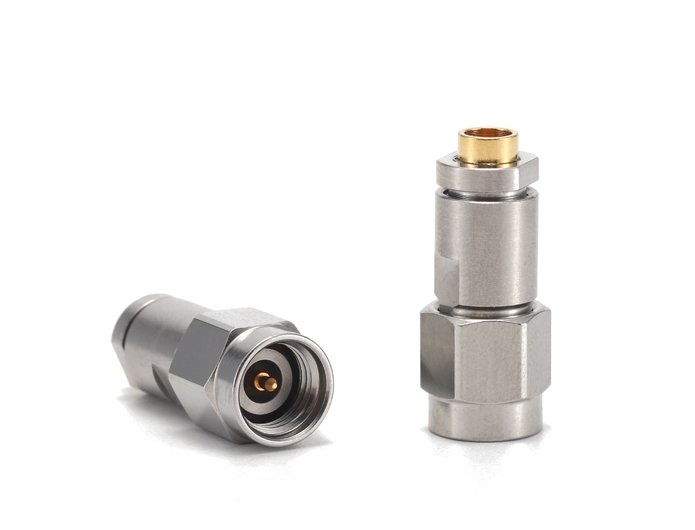
With options like SMA, N-Type, and 2.92mm available, picking the right one feels complex and mistakes can be costly. SMA is common up to 18 GHz, N-Type is larger and robust for power/outdoor use up to 11-18 GHz, while 2.92mm offers precision performance up to 40 GHz and is mechanically compatible with SMA. Already know
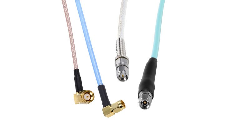
SMA connectors/adapters and cable assemblies are crucial components widely used in RF testing and measurement applications. These connectors are known for their miniature size, wide frequency range, and excellent electrical performance.
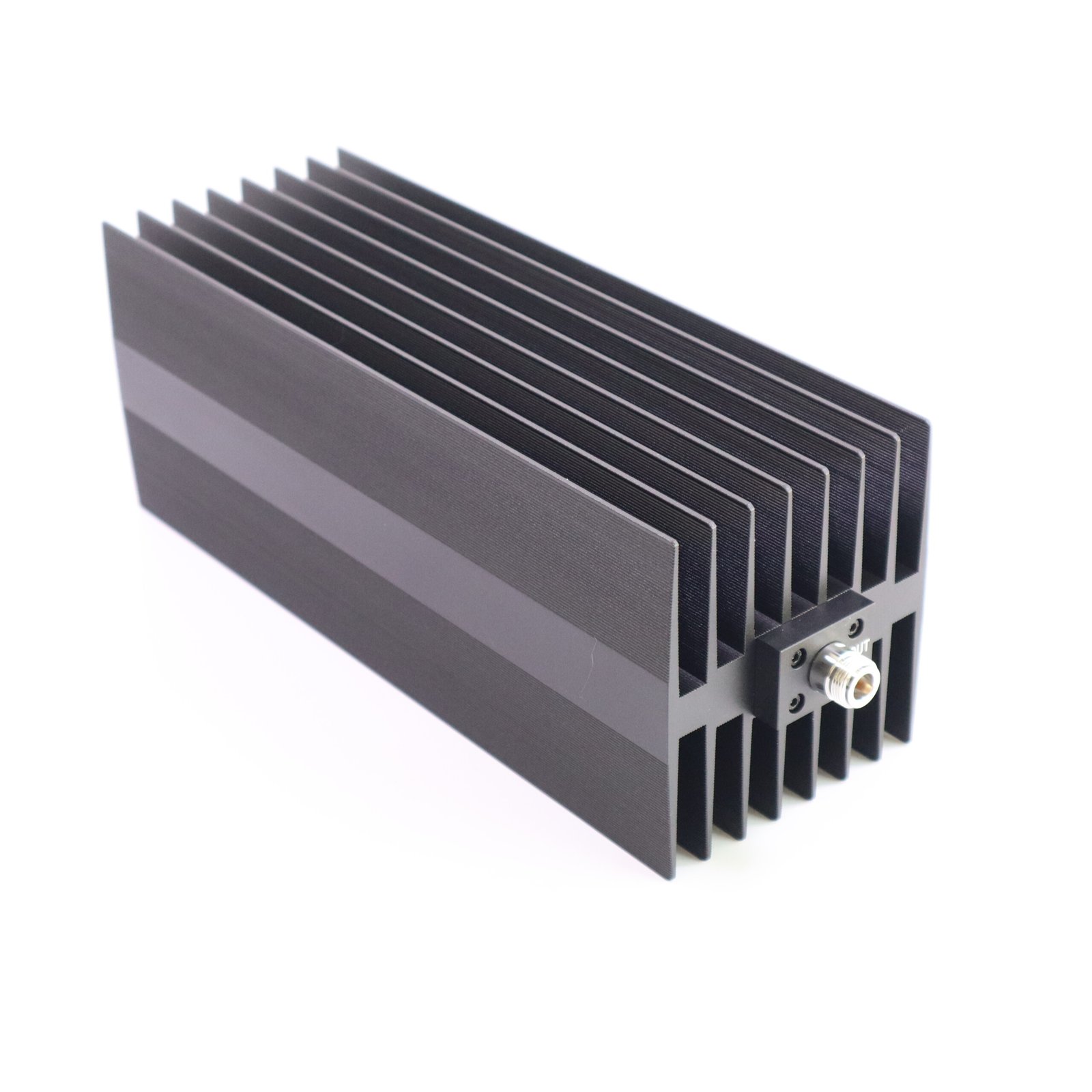
RF attenuators are essential components in many RF and microwave systems, designed to reduce the power of a signal without significantly affecting its integrity. Whether in test equipment, communication systems, or for signal protection, RF attenuators play a key role in ensuring optimal system performance. In this article, we will explore what an RF attenuator

RF, microwave, and millimeter-wave describe frequency ranges with distinct uses. RF covers 3 kHz to 300 GHz, including microwaves and mmWave. Microwaves occupy 300 MHz to 300 GHz, while mmWave strictly focuses on 30 GHz to 300 GHz. Each handles specific tech needs.
