by Angela
Share
An assembly can look perfect, pass continuity, and still fail in your system. Disputes then start over whose measurement is right.
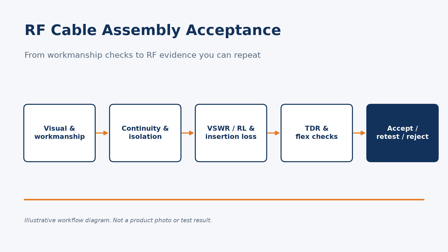
Verify RF cable assembly quality by specifying RF tests, not only workmanship: VSWR or return loss and insertion loss across your band, TDR where faults matter, the test conditions behind each number, and a retest rule for results near the limit.
Below, I walk through what each check proves, what to write into the specification, and how to handle borderline readings.
Why can't visual inspection and continuity alone prove an RF cable assembly is good?
Incoming inspection often stops at looks and a beeper test. Those checks miss the faults that actually degrade an RF link.
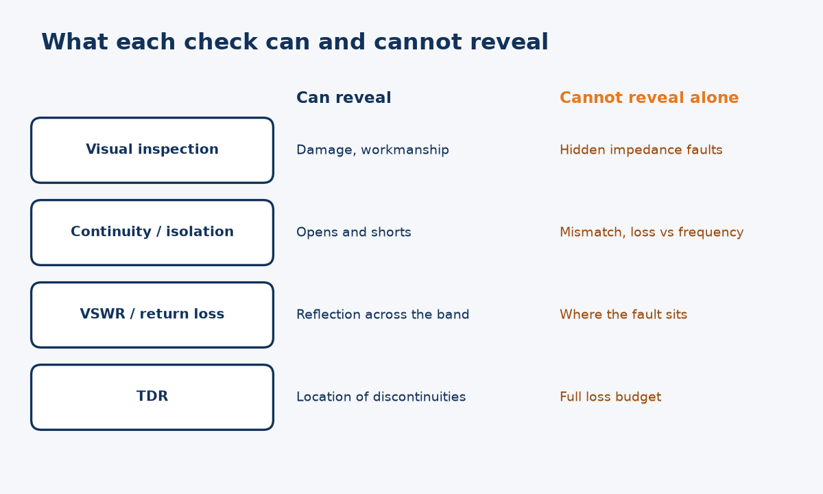
Visual checks confirm workmanship and continuity confirms DC paths, but neither measures impedance match or loss versus frequency. An RF assembly needs RF measurements, because a defect inside a connector can be invisible and still pass continuity.
What the reference standards separate
NASA-STD-8739.4A is useful here because it lists the checks separately. For coaxial assemblies it names continuity, isolation and dielectric withstanding voltage, and then, as distinct items, insertion loss, VSWR and time-domain reflectometry, each "as specified" in the engineering documentation. The structure tells you something: DC and insulation tests answer a different question from RF tests.
Visual and DC checks remain valuable. They catch damaged jackets, wrong connectors, poor crimps and shorts cheaply. But a slightly mis-seated center contact, a deformed dielectric or a poorly prepared cable end can leave continuity intact while creating an impedance step. The same NASA standard also warns that a jacket trapped inside a clamp can cold-flow and loosen the connection over time, producing intermittent faults that a single static check may not catch.
My reading is that an acceptance plan should treat visual and DC checks as screening, and RF measurements as the actual performance evidence. If your RF requirement matters, it should be measured, not inferred from good workmanship. For background on assembly construction, see our RF cable assembly guide.
Which RF tests should an acceptance specification name?
Many purchase orders say only "tested OK". That leaves the supplier to choose the tests, the band and the limit.
Name VSWR or return loss and insertion loss, each with a frequency band and limit; add TDR if you need to locate discontinuities; and include continuity, isolation and withstanding voltage where relevant. State the units and the limit so both parties judge the same number.
Turning tests into a specification
The table below maps each test to what it shows and what to write down. It follows the test list in NASA-STD-8739.4A sections 13.8.8 and 18.2.3, which requires assemblies to pass VSWR, insertion loss and other tests specified by the engineering documentation.
| Test | What it shows | What to specify |
|---|---|---|
| Continuity / isolation | Opens, shorts | Pass criteria, test voltage |
| Withstanding voltage | Insulation integrity | Voltage, duration, leakage limit |
| VSWR or return loss | Reflection across band | Band, limit, point count |
| Insertion loss | Loss across band | Band, maximum loss vs length |
| TDR | Location of impedance steps | Impedance window, when required |
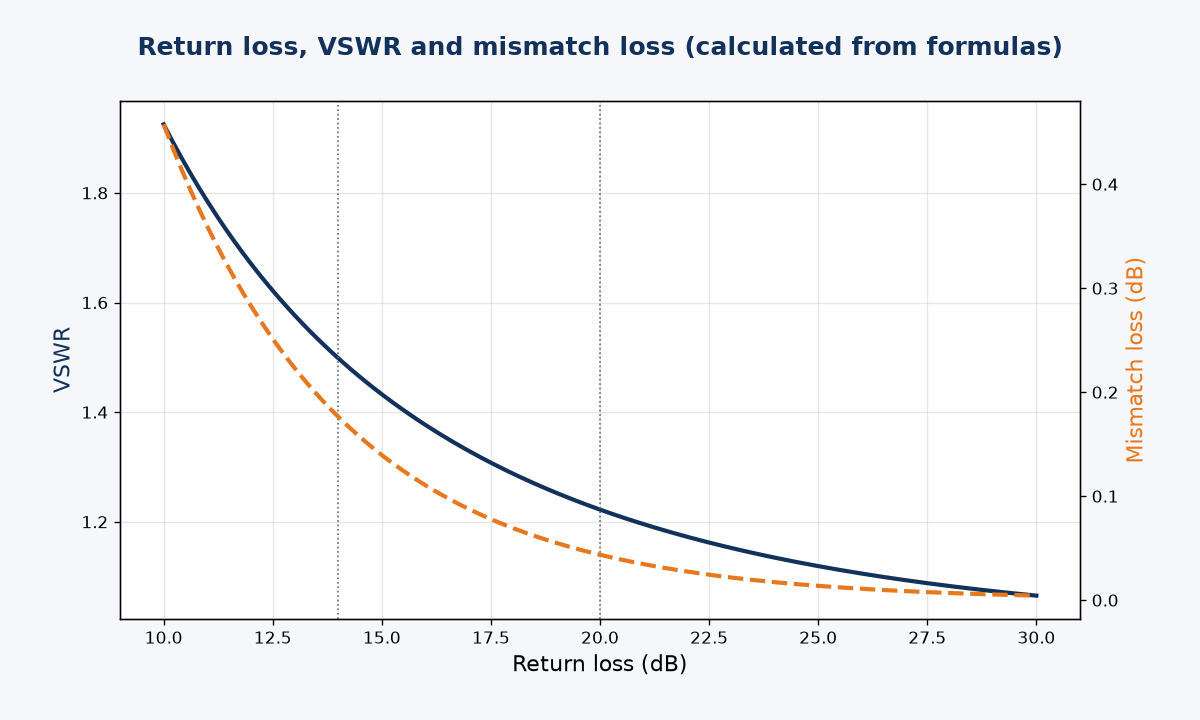
Return loss and VSWR describe the same reflection, so pick one unit and state the conversion. As a hypothetical example, not Reach Line data: a 20 dB return-loss limit equals |Γ| of 0.100, a VSWR of about 1.22 and roughly 0.04 dB of mismatch loss; a 14 dB limit equals VSWR of about 1.50 and roughly 0.18 dB. The chart shows that power lost to mismatch is small, so tight reflection limits are mainly about system matching and ripple, not raw power. Our VSWR vs return loss article explains the terms in more depth. Whatever unit you choose, list the frequency points or sweep settings too, because a limit met at a few spot frequencies says little about the full band.
How do test conditions change the result you measure?
A supplier reports a pass, your bench reads a fail. Often neither side is wrong; they measured under different conditions.
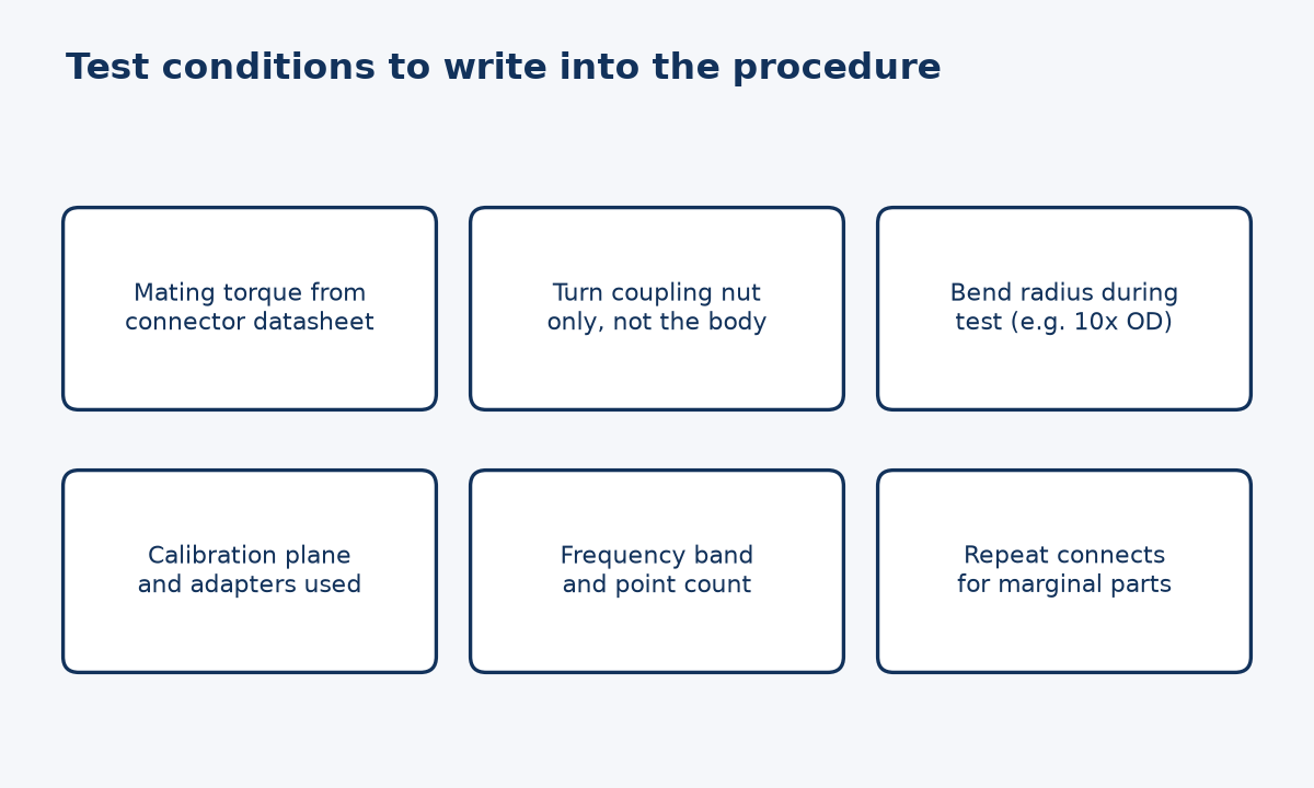
Torque, how the connector is mated, cable bend during test, calibration plane and adapters all shift readings. Write these conditions into the acceptance test procedure so the supplier's data and your incoming test describe the same measurement.
The conditions that make numbers comparable
NASA-STD-8739.4A states that mating torque comes from the engineering documentation, with the connector manufacturer's datasheet as the recommended basis, and that only the coupling nut should be turned while mating. Rotating the connector body can wear interfaces and change the reading. The same standard gives coaxial bend radius guidance of ten times the outside diameter as optimum and six times as a minimum, which is a reasonable starting point to state for test fixturing.
Calibration matters just as much. If one lab calibrates at the end of its test port cables and another includes an adapter, they are measuring slightly different things. NIST research by Koepke and Jargon breaks random variation in repeated S-parameter measurements into components from calibration, disconnect-reconnect and repeat measurements, which shows these are separate, real sources of spread.
In my view, the practical step is to ask the supplier for its acceptance test procedure and compare it with yours before the first shipment. NASA's standard has the procuring agency review acceptance test procedures, and commercial buyers can adopt the same habit. If you need to discuss procedures with us, use the contact page.
What should you do when a measurement is close to the limit?
A reading just over or just under the limit triggers arguments. Rejecting or accepting on one connection can be the wrong call.
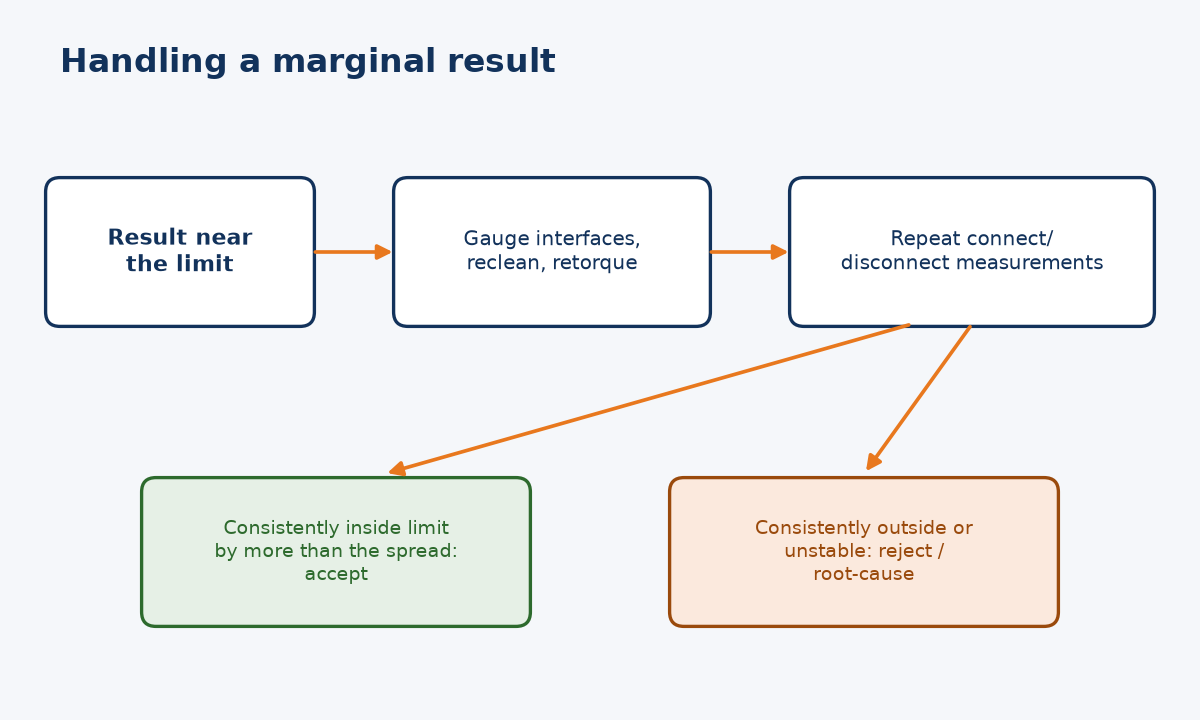
Check the interfaces first, then repeat the measurement with several connect-disconnect cycles. Accept only when results stay inside the limit by more than their spread; reject or investigate when they stay outside or vary widely. Agree this retest rule before parts ship.
Why one reading is not enough
NIST work by Lewandowski and Williams identifies connector repeatability as a primary source of random error in coaxial S-parameter measurements, using repeated connections to characterize it. That means a single marginal reading carries uncertainty from the connection itself, not only from the assembly under test.
Before retesting, inspect and gauge the interfaces. Connector interface dimensions for many RF series are defined in MIL-STD-348, which remains active and includes gauging requirements. A recessed or protruding center contact can damage your test port and corrupt every later measurement, so gauging protects equipment as well as the result.
Then repeat the measurement several times with fresh connections at the specified torque. If every result sits inside the limit by more than the observed spread, the assembly passes with confidence. If results straddle the limit, the honest conclusion is that your measurement cannot decide, so either tighten the measurement setup or agree a guard band in advance. If results are consistently outside, reject and ask for root cause. Documenting this rule in the purchase agreement turns a dispute into a procedure. You can review our published quality control page alongside your own requirements.
Conclusion
Write tests, band, conditions and a retest rule into your order, and an RF cable assembly quality check becomes evidence both sides can reproduce.
STAY IN FOR MORE NEWS
Subscribe to our free newsletter.

In the world of high-frequency communication systems, **RF cables** are often the unsung heroes that carry critical signals. Whether it's for wireless communication, satellite links, or laboratory setups, selecting the right RF cable can make or break the reliability and performance of your system.

First of all, in the OTA environment, it is necessary to establish communication between the corresponding measurement tool and the measuring device, and then perform the corresponding measurement through the air test.

As a flexible customer-focused company, we offer several options to meet your different needs.
Choosing the wrong RF adapter can ruin your signal integrity. With so many connector types, how do you pick the right one? Let's simplify the process.
