by Angela
Share
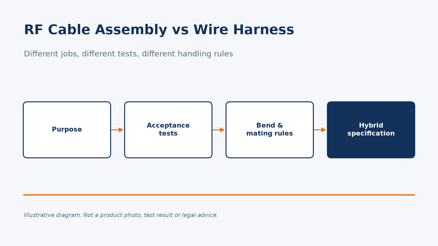
An RF cable assembly and a wire harness can look alike on a drawing. Specify one like the other and the wrong tests get run.
A wire harness organizes many conductors into one installable unit and is accepted on continuity and insulation tests. An RF cable assembly is a controlled-impedance coaxial line, accepted on RF tests such as insertion loss, VSWR and TDR, with stricter bend and mating rules.
The sections below compare purpose, tests, handling and hybrid specifications.
What actually separates an RF cable assembly from a wire harness?
Both look like cables with connectors on the ends. Treating them as the same product leads to the wrong specification and the wrong tests.
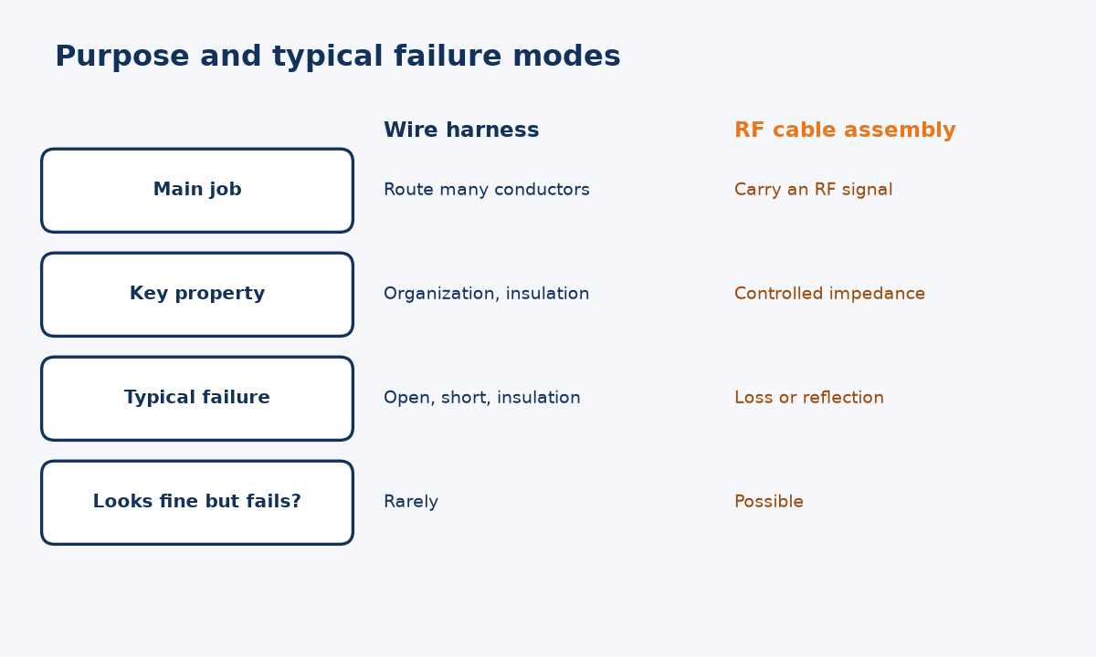
A wire harness routes and organizes many conductors for power and signals as one unit. An RF cable assembly is a coaxial transmission line with RF connectors, built to keep impedance controlled so high-frequency signals pass with low loss and reflection.
Definitions that clarify the difference
NASA-STD-8739.4A defines a harness as one or more insulated wires or cables, with or without twist, covering or breakouts, assembled with two or more termination devices and arranged so it can be handled as one assembly. That definition is about organization: getting many conductors to the right places as a single installable unit.
An RF cable assembly answers a different question. Its job is to carry a radio-frequency signal from one port to another while preserving it. Coaxial cable does this by keeping the inner conductor, dielectric and outer conductor in a fixed geometry, so the line has a defined characteristic impedance. Any change in that geometry, at a connector, a crimp or a sharp bend, appears as a reflection.
In my view, the most useful way to tell them apart is to ask what failure looks like. A harness usually fails as an open, short or insulation breakdown. An RF assembly can pass all of those checks and still fail because loss or reflection is too high at its operating frequency. For more on assembly construction, see our RF cable assembly guide.
How do acceptance tests differ between the two?
Buyers often reuse a harness test plan for coaxial parts. That plan checks the wrong properties for an RF signal path.
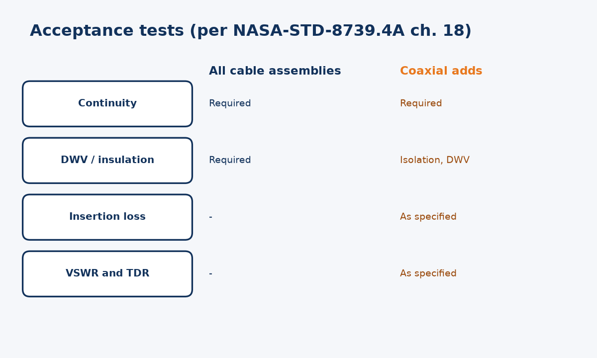
Harness and cable assemblies are normally accepted on continuity, dielectric withstanding voltage and insulation resistance. Coaxial assemblies add RF measurements such as insertion loss, VSWR and time-domain reflectometry, defined in the engineering documentation.
What the standard lists for each
NASA-STD-8739.4A section 18.2.1 requires all cable assemblies to meet continuity, dielectric withstanding voltage and insulation resistance tests before acceptance, and points to 18.2.3 for coaxial exceptions. Section 18.2.3 then lists continuity, isolation, withstanding voltage, insertion loss, VSWR and TDR for coaxial assemblies, as specified in the engineering documentation.
| Check | Wire harness | RF cable assembly |
|---|---|---|
| Continuity | Yes | Yes |
| Withstanding voltage / insulation | Yes | Yes (isolation, DWV) |
| Insertion loss | Not typical | Yes, across the band |
| VSWR / return loss | Not typical | Yes, across the band |
| TDR | Not typical | Yes, when specified |
The RF tests also bring a measurement issue harness testing rarely faces. NIST research by Lewandowski and Williams identifies connector repeatability as a primary source of random error in coaxial S-parameter measurements. So an RF test plan should state torque, calibration and retest rules, not just limits. A continuity tester gives the same answer every time; a network analyzer reading depends on how the connection was made.
This has a practical consequence for sourcing. A harness supplier with excellent continuity and hipot test stations may still lack calibrated RF test equipment, fixtures and procedures for coaxial legs. Before awarding an RF assembly to a harness shop, or the reverse, ask which of these tests they perform in-house, over what frequency range, and how results are recorded for each serial number.
How do design and handling rules differ?
Routing a coaxial line like a power bundle can quietly change its electrical behavior, even if nothing looks damaged.
Coaxial lines need gentler bends, controlled connector mating and defined interface dimensions. NASA's bend table allows harnesses without coax to bend to 3x their diameter, while individual coaxial cable has a 6x minimum and 10x optimum.
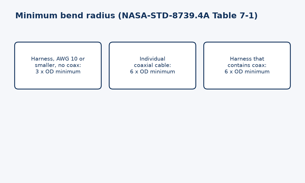
Bend radius, mating and interfaces
Table 7-1 of NASA-STD-8739.4A makes the contrast concrete. An overall harness with AWG 10 or smaller wires and no coaxial cable has an optimum bend radius of 10 times its outside diameter and a minimum of 3 times. An individual coaxial cable has the same 10 times optimum but a 6 times minimum. A harness containing coaxial cable inherits the 6 times minimum. The tighter limit exists because bending a coax deforms the dielectric and shifts the conductors, which changes impedance.
Mating also differs. The same standard says coaxial connector mating torque comes from the engineering documentation, with the manufacturer's datasheet recommended, and that only the coupling nut should be rotated. Harness connectors are usually judged on retention and contact integrity rather than on how a reflection changes with torque.
Finally, RF connector interfaces are dimensionally defined. MIL-STD-348 sets interface dimensions, including gauging, for many RF connector series. A harness connector mismatch typically prevents mating; an RF interface slightly out of tolerance may still mate but degrade performance or damage the mating port.
When do you need both, and how should you specify a hybrid?
Many systems route RF lines inside a larger harness. Specifying the bundle only as a harness leaves the RF legs unprotected in the requirements.
When coaxial lines run inside a harness, specify the bundle with harness rules and each coaxial leg with RF requirements: band, insertion loss, VSWR or return loss, connector interfaces, and the coaxial bend limit for the whole bundle.
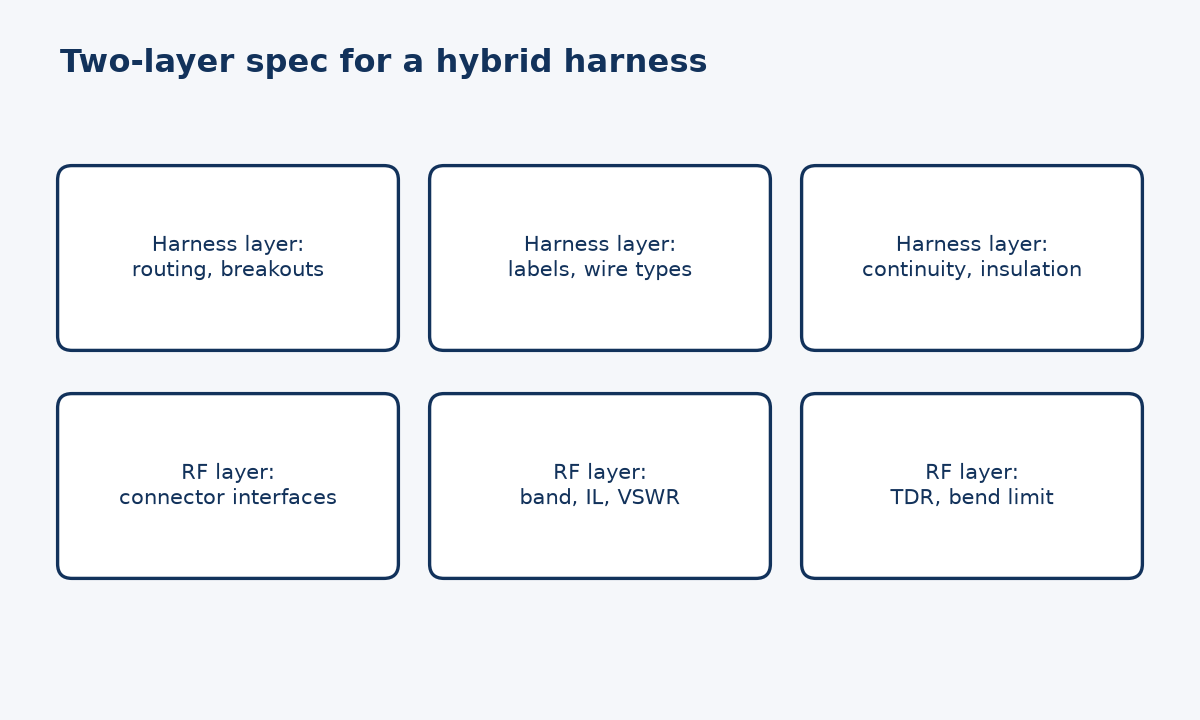
Writing one specification for two behaviors
A hybrid assembly is common in equipment where power, control and RF signals travel together. NASA-STD-8739.4A handles this case in Table 7-1: an overall harness containing coaxial cable takes the coaxial minimum bend radius of 6 times the outside diameter, not the 3 times allowed for small-gauge wire-only bundles. The most sensitive conductor sets the rule for the whole bundle.
I suggest treating the specification in two layers. The harness layer covers routing, breakouts, labeling, wire types, continuity and insulation tests. The RF layer lists every coaxial leg with its connector interfaces, frequency band, insertion-loss and reflection limits, and whether TDR is required. The standard's requirement that acceptance test records be traceable to the assembly tested (section 18.2.5) is useful for both layers.
This structure also makes supplier quotes easier to compare, because each supplier is pricing the same RF tests rather than assuming a harness test is enough. If you are planning a hybrid build, our contact page is the place to share drawings and requirements.
Conclusion
Specify harnesses for organization and insulation, RF assemblies for signal integrity, and give hybrid bundles both layers so no requirement falls between them.
STAY IN FOR MORE NEWS
Subscribe to our free newsletter.
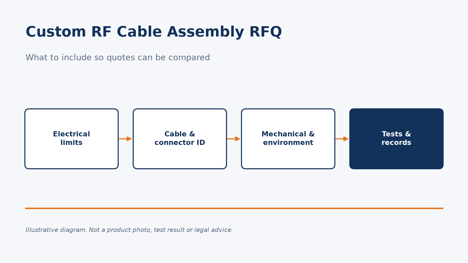
A checklist for custom RF cable assembly quote requests: electrical limits, part identity, mechanical and environmental details, and test records.
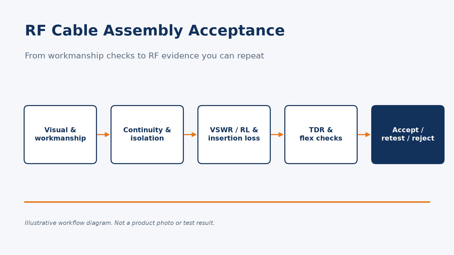
Which tests, conditions and retest rules turn an RF cable assembly quality check into acceptance evidence you can repeat.

In the world of high-frequency communication systems, **RF cables** are often the unsung heroes that carry critical signals. Whether it's for wireless communication, satellite links, or laboratory setups, selecting the right RF cable can make or break the reliability and performance of your system.

First of all, in the OTA environment, it is necessary to establish communication between the corresponding measurement tool and the measuring device, and then perform the corresponding measurement through the air test.
