by Angela
Share
Vague quote requests produce quotes that cannot be compared, and first articles that miss what you needed.
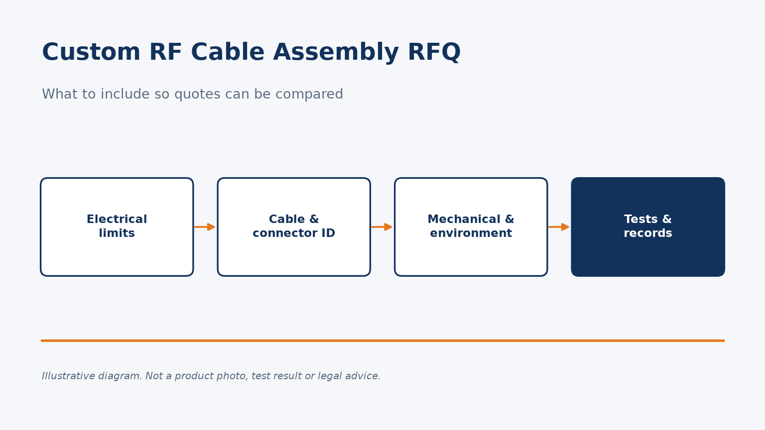
A custom RF cable assembly quote request should state electrical limits with their frequency band, exact cable and connector identity, length convention and tolerance, installation and environmental conditions, and the tests and records each unit must ship with.
Here is what to include in each part of the request, and why.
Which electrical requirements should the quote request state?
A request that says only "SMA to SMA, 1 meter" invites quotes that cannot be compared. Each supplier fills the gaps differently.
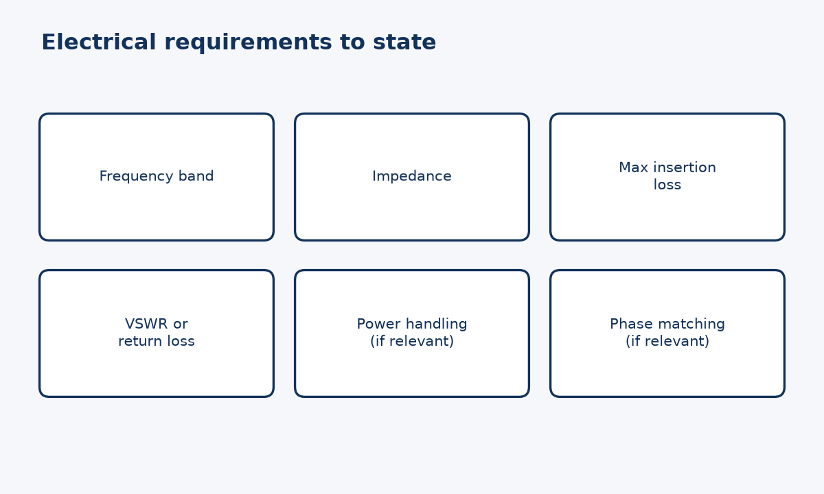
State the frequency band, impedance, maximum insertion loss, the reflection limit as VSWR or return loss, and any power or phase requirements. Say which of these must be tested on every unit, so suppliers price the same verification.
Turning performance into numbers suppliers can quote
Coaxial assembly testing in NASA-STD-8739.4A section 18.2.3 lists continuity, isolation, withstanding voltage, insertion loss, VSWR and TDR, each "as specified in the engineering documentation". The phrase matters for buyers: the standard expects the requirement to come from the purchaser's documents, not the supplier's defaults. A quote request is often the first such document.
For each electrical parameter I recommend writing three things: the limit, the frequency range over which it applies, and whether it is verified per unit, by sample, or by design. "VSWR 1.3:1 maximum" is incomplete; "VSWR 1.3:1 maximum from the lowest to highest operating frequency, 100% tested" can be priced. The numbers in that example are illustrative, not a recommendation; your system budget sets the real values.
If phase matching between assemblies, power handling or shielding effectiveness matters in your application, say so explicitly. These requirements can change cable choice, construction and test cost substantially, and suppliers cannot infer them from connector types. Our VSWR vs return loss article explains the reflection terms.
How should you identify the cable and connectors?
"RG-type cable with N connectors" can describe dozens of constructions. Ambiguous part identity is a common cause of mismatched samples.
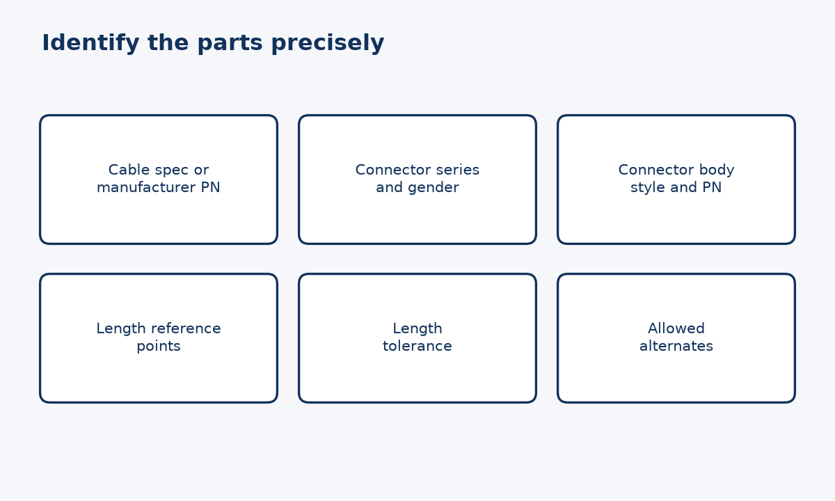
Identify the cable by a specification part number or the manufacturer's part number, and each connector by interface series, gender, body style and part number. Define length with its reference points and tolerance, so every supplier measures the same thing.
Specification numbers remove guesswork
Military specifications give a shared vocabulary. MIL-DTL-17, the general specification for flexible and semirigid RF cables, uses a part number made of "M", the specification number, a slash-sheet number and a dash or RG number, for example M17/28-RG058. Quoting a full number like this tells every supplier exactly which construction is meant, even if you accept equivalents.
For connectors, MIL-STD-348 defines interface dimensions for many RF connector series. Naming the interface series and gender settles mating compatibility; the connector part number then settles body style, cable attachment method and materials. If you allow alternates, say what must stay identical, such as interface, impedance and termination style.
Length needs equal care. State whether it is measured between connector reference planes, connector tips or another point, and give a tolerance. In my analysis this is one of the easiest details to leave out and one of the most likely to cause a rejected first article, because each supplier may assume a different convention. A simple dimensioned sketch attached to the request is usually clearer than words.
What mechanical and environmental details matter?
An assembly that measures well on the bench can still fail after installation if routing and environment were never described.
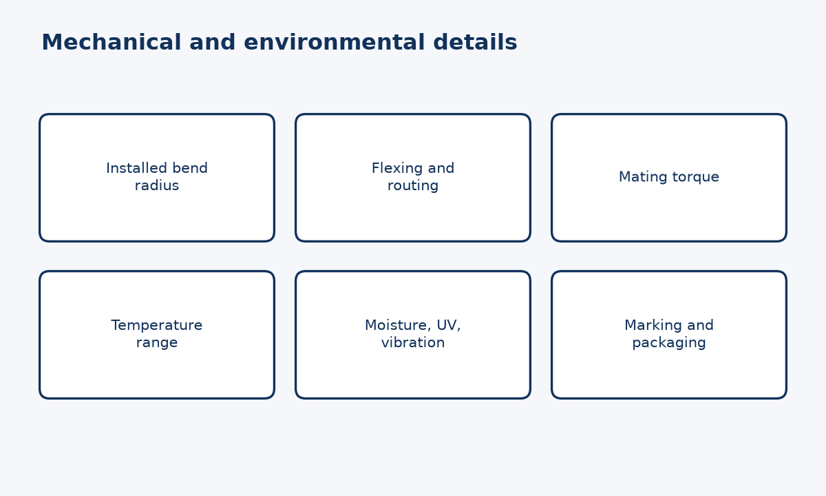
Describe minimum installed bend radius, routing and flexing, connector mating torque, environmental exposure such as temperature range, and any jacket, marking or labeling needs. For semi-rigid parts, say whether preconditioning is required.
Information the supplier cannot see
NASA-STD-8739.4A Table 7-1 gives an individual coaxial cable an optimum bend radius of 10 times its outside diameter and a minimum of 6 times. If your installation forces a tighter bend, the supplier needs to know before choosing cable, because a bend that is tight for one construction may be fine for another. The same standard requires semi-rigid coaxial cable to be preconditioned by thermal cycling (section 7.2.13), which is worth stating if your application is thermally demanding.
Mating torque is another detail to write down. The standard says coaxial connector mating torque is defined in the engineering documentation, with the connector manufacturer's datasheet recommended, and that only the coupling nut should be turned. Including this in the request aligns how the supplier tests with how your installers will mate the part.
Finally, list exposure conditions: operating and storage temperature, moisture, vibration, ultraviolet light or chemicals, as relevant. I would rather see a short honest list than a generic "harsh environment" label, because only specific conditions can be designed and priced. Labeling, marking and packaging needs belong here too.
What test data and records should you ask for?
Two suppliers can both promise "100% tested" and mean very different things. The difference shows up only when a part fails.
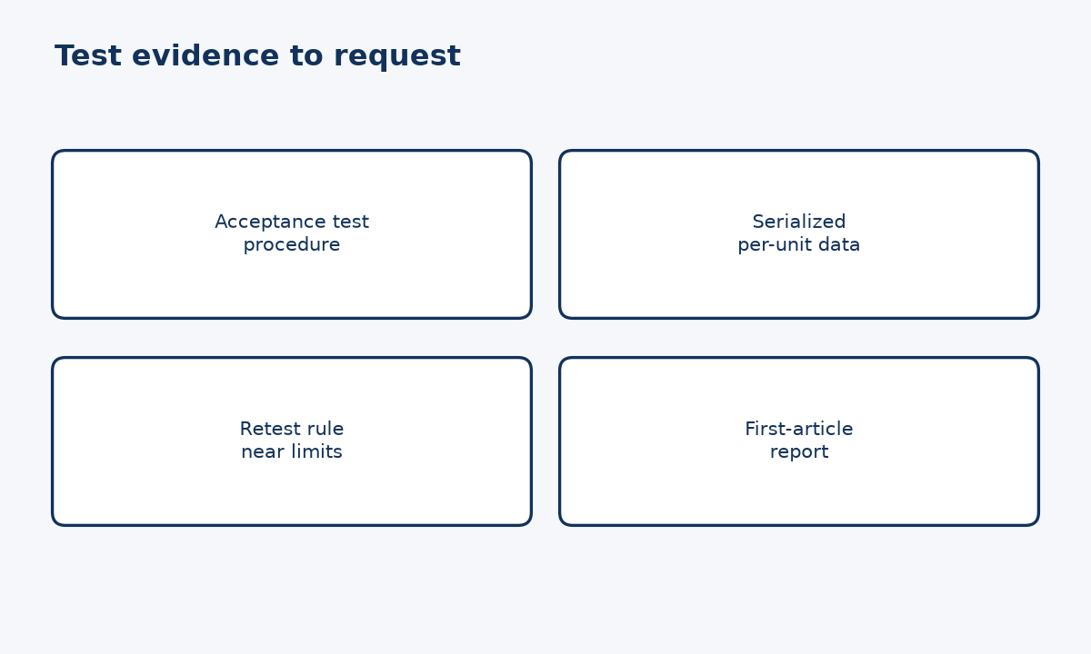
Ask which tests are performed, under what conditions, and what record each unit ships with. Request the acceptance test procedure for review, serialized results traceable to each assembly, and a retest rule for results near the limit.
Records that make test claims checkable
NASA-STD-8739.4A has acceptance test procedures made available to the procuring agency for review before use (section 18.2.2) and requires test records to be complete and traceable to the specific assembly (section 18.2.5). Commercial buyers can borrow both habits without adopting the whole standard. Reviewing the procedure before the first order shows whether the supplier tests across your full band, with what calibration, and at what torque, while there is still time to align expectations rather than argue after delivery.
| Item to request | Why it matters |
|---|---|
| Acceptance test procedure | Shows tests, band, torque, calibration |
| Per-unit data (serialized) | Lets you trace a field failure |
| Retest rule near limits | Avoids disputes on marginal parts |
| First-article report | Confirms build before volume |
Test conditions deserve attention because RF readings are sensitive to them. NIST research by Lewandowski and Williams identifies connector repeatability as a primary source of random error in coaxial S-parameter measurements. That is why asking for the test conditions, not just the pass/fail result, is reasonable. When you are ready to send a request, our contact page lists how to reach us, and the catalogue shows published product ranges.
Conclusion
A precise request costs an hour to write and saves weeks of rework: limits with bands, exact parts, real installation conditions, and checkable test records.
STAY IN FOR MORE NEWS
Subscribe to our free newsletter.
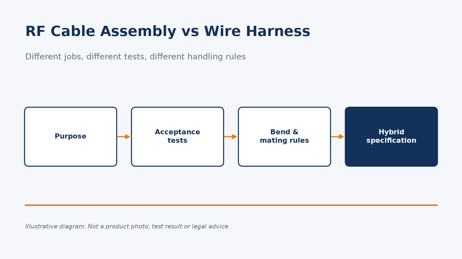
RF cable assemblies and wire harnesses differ in purpose, acceptance tests, bend limits and interfaces. Here is how to specify each, and hybrids.
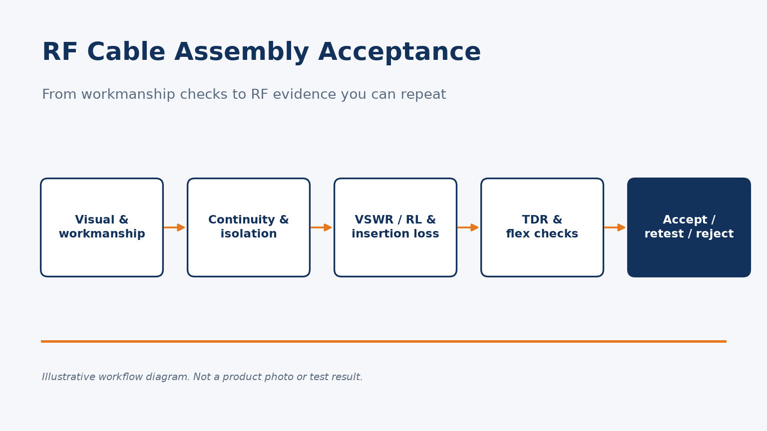
Which tests, conditions and retest rules turn an RF cable assembly quality check into acceptance evidence you can repeat.

In the world of high-frequency communication systems, **RF cables** are often the unsung heroes that carry critical signals. Whether it's for wireless communication, satellite links, or laboratory setups, selecting the right RF cable can make or break the reliability and performance of your system.

First of all, in the OTA environment, it is necessary to establish communication between the corresponding measurement tool and the measuring device, and then perform the corresponding measurement through the air test.
