
by Angela
Share
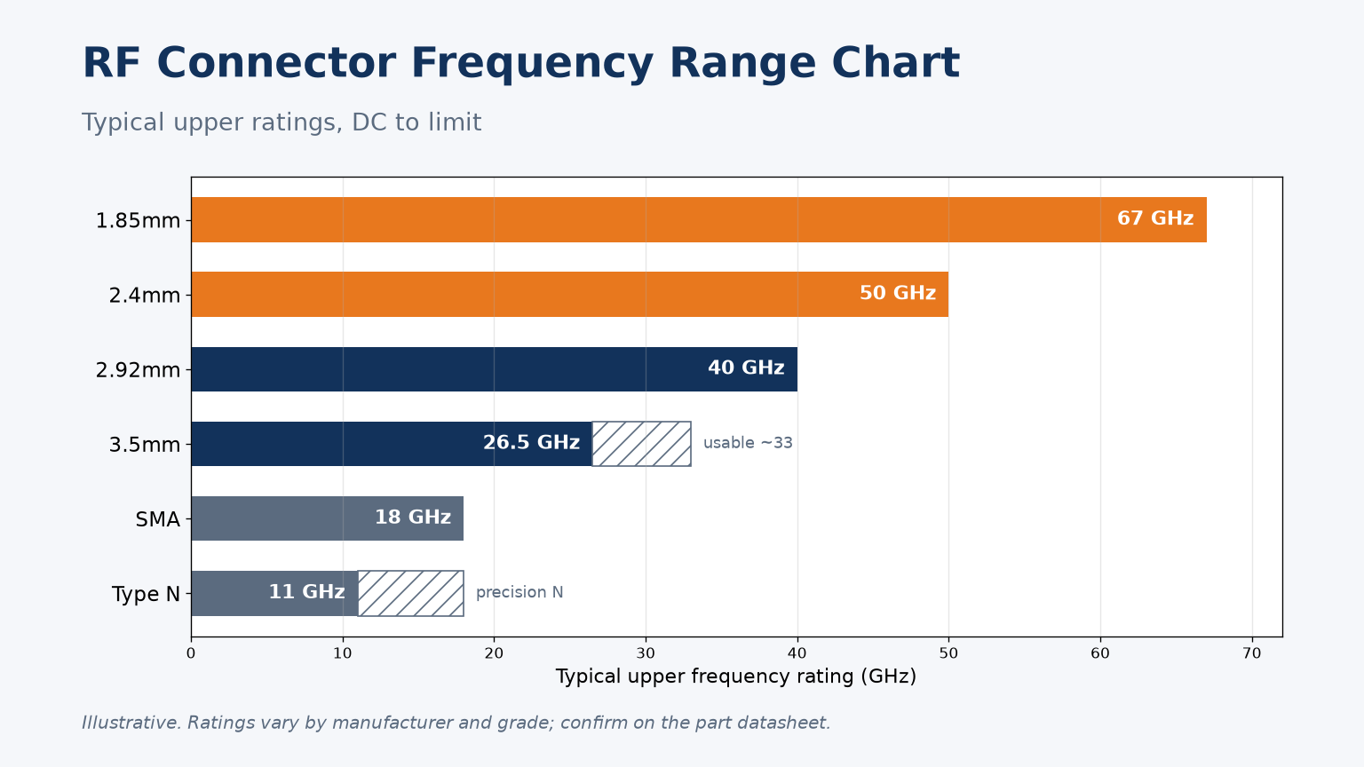
Choosing a connector from its size or price, instead of its frequency limit, is how 40 GHz systems end up working to 18 GHz.
Typical upper ratings are 11 GHz for standard Type N, 18 GHz for SMA and precision N, 26.5 GHz for 3.5mm, 40 GHz for 2.92mm, 50 GHz for 2.4mm and 67 GHz for 1.85mm.
Here is the chart, the physics behind it, the mating groups and how to use it.
What frequency range does each common RF connector cover?
Every coaxial connector works from DC up to a limit. The limit, not the size or price, is usually what decides the choice.
Typical upper ratings are: Type N 11 GHz (precision N 18 GHz), SMA 18 GHz, 3.5mm 26.5 GHz, 2.92mm 40 GHz, 2.4mm 50 GHz and 1.85mm 67 GHz. Ratings vary by maker and grade, so confirm them on the datasheet.
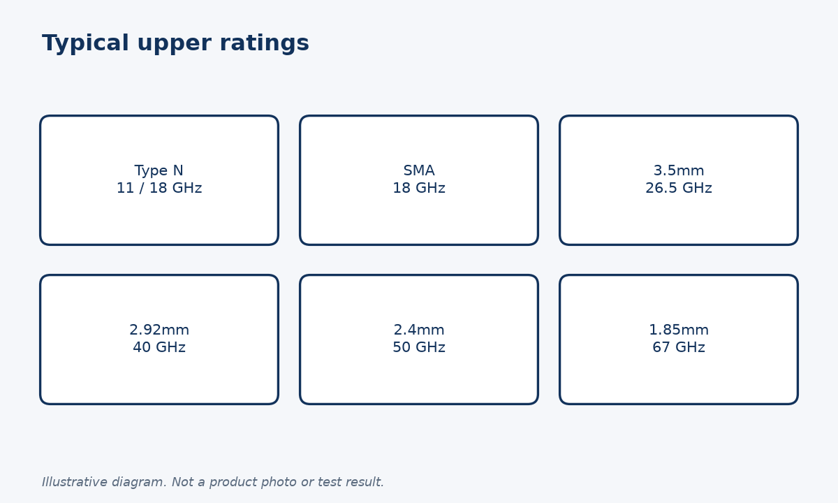
The chart
| Connector | Typical upper rating | Notes | Mates directly with |
|---|---|---|---|
| Type N | 11 GHz standard, 18 GHz precision | Rugged, larger body | N only (50 ohm) |
| SMA | 18 GHz | Some legacy parts lower; precision versions to 26.5 GHz or more | 3.5mm, 2.92mm |
| 3.5mm | 26.5 GHz | Usable to about 33 GHz | SMA, 2.92mm |
| 2.92mm | 40 GHz | Air dielectric | SMA, 3.5mm |
| 2.4mm | 50 GHz | Air dielectric | 1.85mm |
| 1.85mm | 67 GHz | Air dielectric | 2.4mm |
National metrology work mirrors these limits. NIST's NISTIR 6613 describes a 2.92mm power calibration service from 0.05 to 40 GHz and notes that its highest-frequency coaxial power detectors use the 2.4mm connector, over a range that includes 0.5 to 50 GHz. A NIST paper on a direct comparison system up to 67 GHz covers power sensors with 1.85mm connectors up to 67 GHz.
Our catalogue follows the same ladder: N and SMA-to-N adapters such as the N right-angle adapter are rated DC to 18 GHz, the 2.92mm bulkhead adapter DC to 40 GHz, the 2.4mm adapter DC to 50 GHz and the 1.85mm adapter DC to 67 GHz. For a broader overview of the connector families, see RF connector types explained.
Two practical points sit behind the table. Many charts quote SMA at 12 GHz, which reflects older or general-purpose parts; most modern SMA components, including the SMA adapters and attenuators in our catalogue, are specified to 18 GHz or higher. Type N is similar: a standard N is usually rated around 11 GHz, while precision N parts reach 18 GHz. The 75 ohm version of N is a different connector with a much lower limit.
Why do smaller connectors reach higher frequencies?
The numbers in the chart are not marketing tiers. They follow from the geometry of the coaxial line inside the connector.
Above a certain frequency a coaxial line supports a higher-order mode (TE11) as well as the wanted TEM mode, and performance becomes unpredictable. That cutoff rises as the conductor diameters shrink, so each smaller connector family gains usable bandwidth.
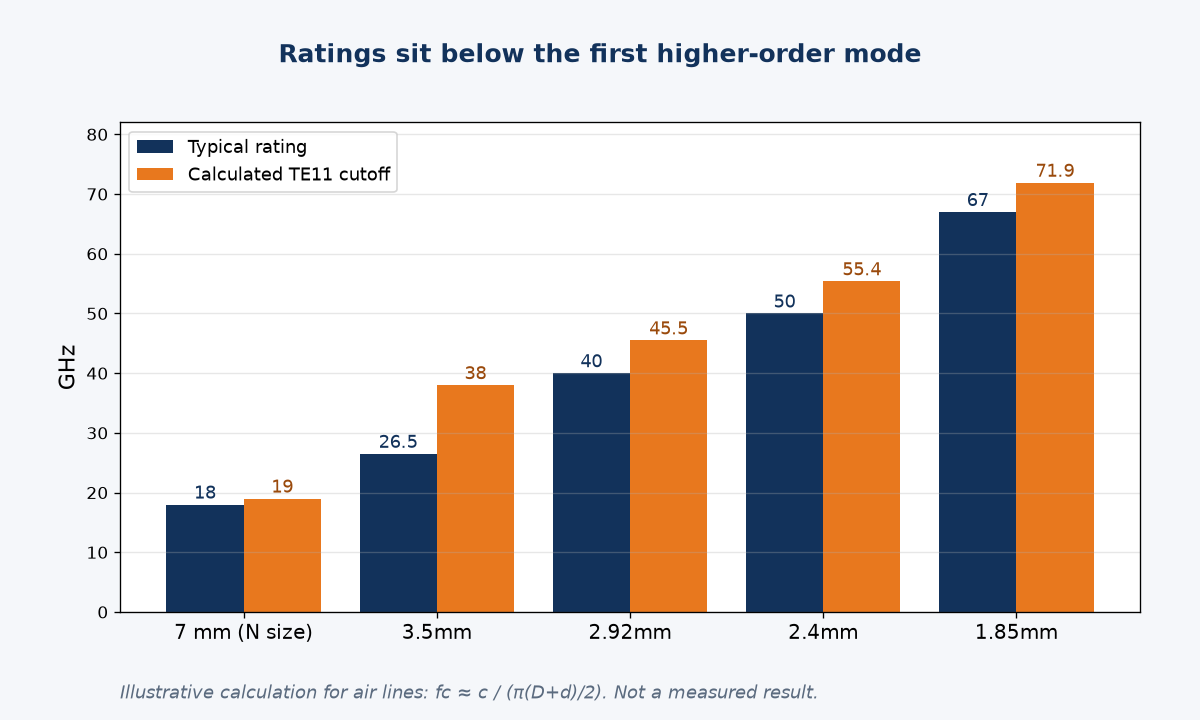
Calculated cutoff versus rating
For an air-filled line, the TE11 cutoff is approximately fc ≈ c / (π · (D + d) / 2), where D is the outer conductor's inner diameter and d the centre conductor diameter. A dielectric lowers it by the square root of its permittivity. Using nominal 50 ohm dimensions, I calculated:
| Air line | D / d (mm) | Approx. TE11 cutoff | Typical rating |
|---|---|---|---|
| 7 mm (precision N size) | 7.00 / 3.04 | 19.0 GHz | 18 GHz |
| 3.5mm | 3.50 / 1.52 | 38.0 GHz | 26.5 GHz |
| 2.92mm | 2.92 / 1.27 | 45.5 GHz | 40 GHz |
| 2.4mm | 2.40 / 1.04 | 55.4 GHz | 50 GHz |
| 1.85mm | 1.85 / 0.80 | 71.9 GHz | 67 GHz |
Every rating sits below its calculated cutoff, which is the margin designers leave for tolerances, beads and transitions. The 3.5mm row also explains a common confusion: its cutoff is high enough that NIST planned a 3.5mm calibration service to 33 GHz, initially offered to 26.5 GHz, as described in NISTIR 5092. Standard Type N uses a PTFE dielectric, which pulls its limit well below the precision air-line value. My advice is to use these calculations to understand the limits, and the part's datasheet to design with. Our article on the engineering behind 1.85mm connectors goes deeper into one of these families.
Which RF connectors can mate with each other?
A connector that threads on is not automatically compatible, and some that look similar must never be mated.
There are three common mating groups: SMA, 3.5mm and 2.92mm intermate; 2.4mm and 1.85mm intermate; Type N mates only with Type N. Moving between groups always needs an adapter, and the adapter's rating becomes part of your system limit.
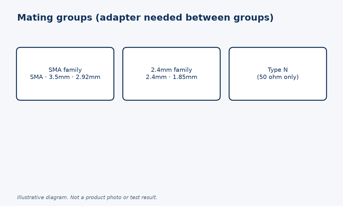
Mating groups and the adapters between them
| Group | Members | Moving to another group |
|---|---|---|
| SMA family | SMA, 3.5mm, 2.92mm | Adapter to N or to 2.4mm |
| 2.4mm family | 2.4mm, 1.85mm | Adapter to 2.92mm or N |
| Type N | 50 ohm N | Adapter to SMA family |
Within a group, the lowest-rated member still sets the frequency limit. A 1.85mm port mated to a 2.4mm cable is a 50 GHz path, not a 67 GHz path. NIST's own 67 GHz power comparison system uses 2.4mm sensors adapted to 1.85mm as transfer standards between 10 MHz and 50 GHz, and switches to WR15 waveguide sensors adapted to 1.85mm from 50 to 67 GHz, a good illustration of using each interface only where it is rated.
Two cautions from experience. First, 50 ohm and 75 ohm Type N connectors look alike but should never be mated; the 50 ohm male pin can damage a 75 ohm female. Second, interface dimensions for mil-spec connectors are controlled by MIL-STD-348, including gauging, and a quick gauge check prevents most mating damage.
For transitions, see our 2.4mm to 1.85mm, 2.4mm to 2.92mm and SMA to N adapter categories, or browse all precision adapters.
How should you use the frequency chart when specifying a system?
The chart answers which connector can reach a frequency. A good specification also asks how well it performs near that limit.
Start from the highest frequency you must support, add margin, and choose the connector whose rating covers it. Then check that every interface in the path, including adapters and attenuators, is rated at least that high, and read VSWR at the top of the band.
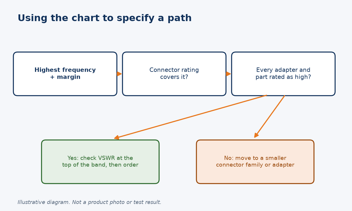
From chart to purchase order
Performance usually degrades toward the top of a connector's range, so rating alone is not enough. Our 50 W SMA fixed attenuator is a good published example: it is offered in DC-4, DC-6, DC-12.4 and DC-18 GHz versions with maximum VSWR of 1.2, 1.25, 1.35 and 1.45 respectively. If your system only needs 6 GHz, the narrower-band version gives a better match than the 18 GHz one.
Map your band to the chart. Our guides to radar bands and to RF, microwave and millimetre wave give the frequency ranges. Work in the X and Ku bands fits SMA and precision N; Ka band work up to 40 GHz needs 2.92mm or smaller throughout; work above 40 GHz moves you into the 2.4mm and 1.85mm family.
The checklist I use is short:
| Step | Question |
|---|---|
| 1 | What is the highest frequency, plus margin? |
| 2 | Which connector rating covers it? |
| 3 | Is every adapter, cable and attenuator rated as high? |
| 4 | What is the VSWR or return loss at the top frequency? |
| 5 | How many matings will the interface see? |
If you send us your frequency range, connector types and genders through our contact page, we will check the path and quote adapters, cable assemblies or attenuators to suit. We reply with part numbers and datasheet values, so you can verify every interface before you order.
Conclusion
Pick the connector whose rating covers your top frequency with margin, then check every interface. Send us your band for a quote.
STAY IN FOR MORE NEWS
Subscribe to our free newsletter.
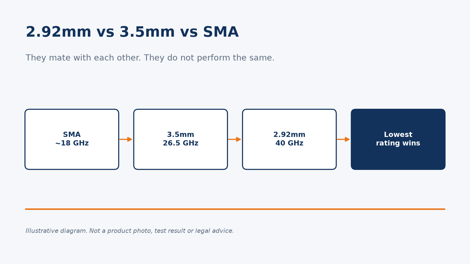
SMA, 3.5mm and 2.92mm connectors intermate, but not at the same frequency. Ratings, mixing rules, torque and when to choose each one.
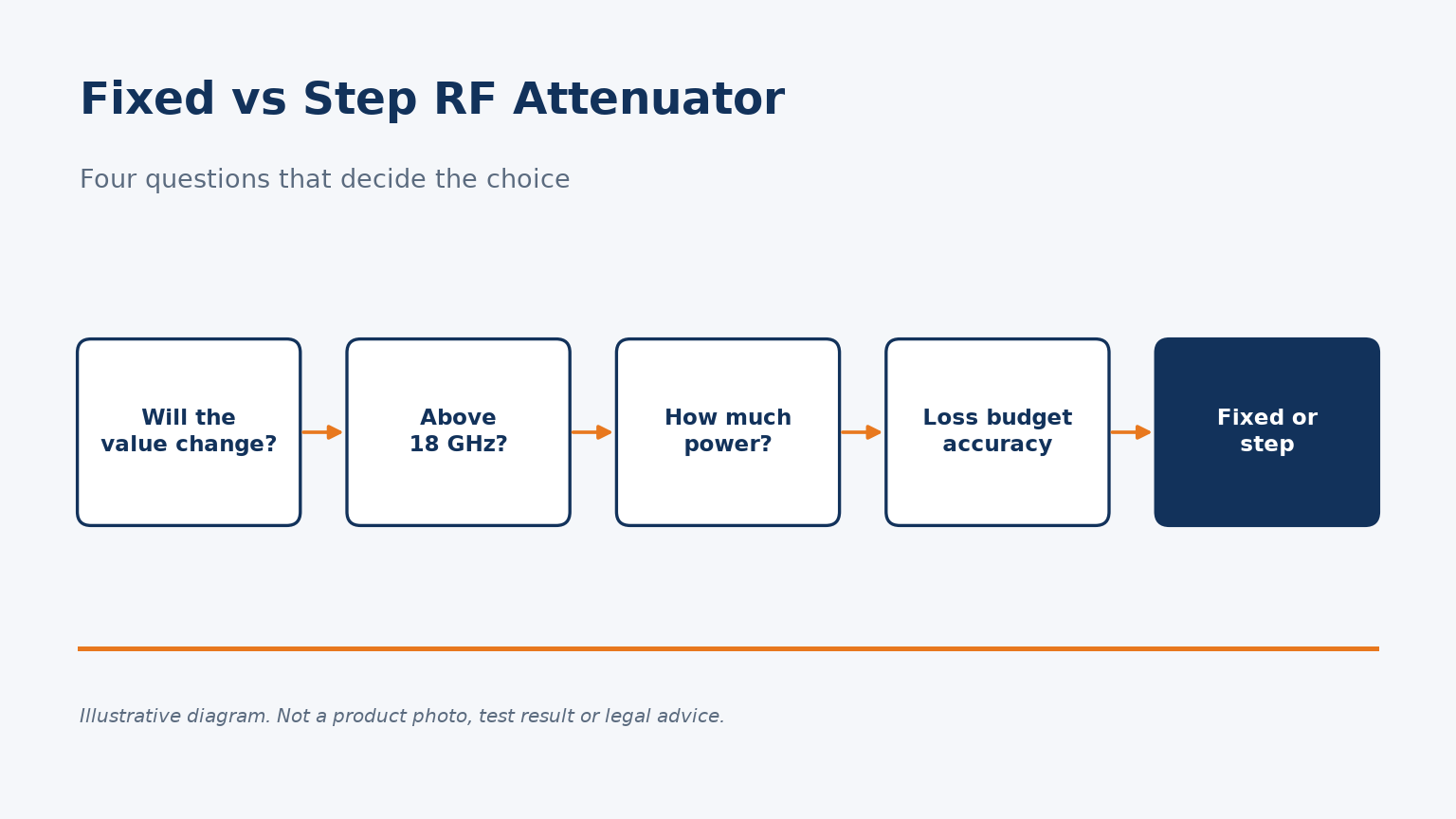
Fixed vs step RF attenuators compared with real specs: incremental vs total loss, mismatch and repeatability, and a decision table by frequency and power.
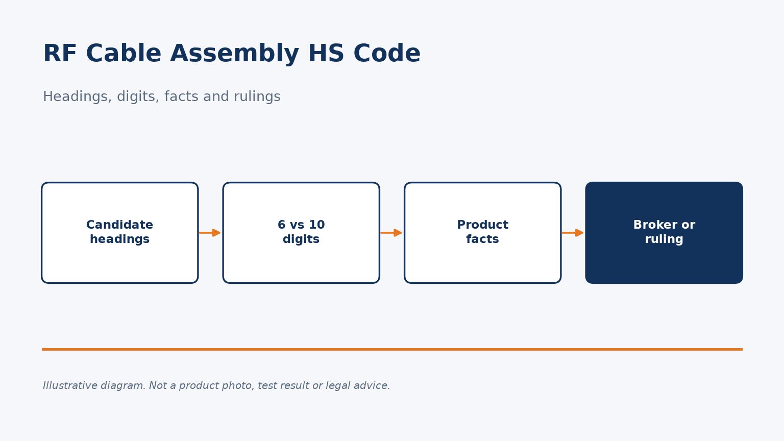
Which HTS headings are considered for RF cable assemblies, why six digits are not enough, which facts matter, and how to get a reliable classification.
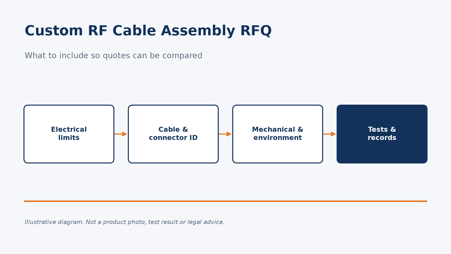
A checklist for custom RF cable assembly quote requests: electrical limits, part identity, mechanical and environmental details, and test records.
