
by Angela
Share
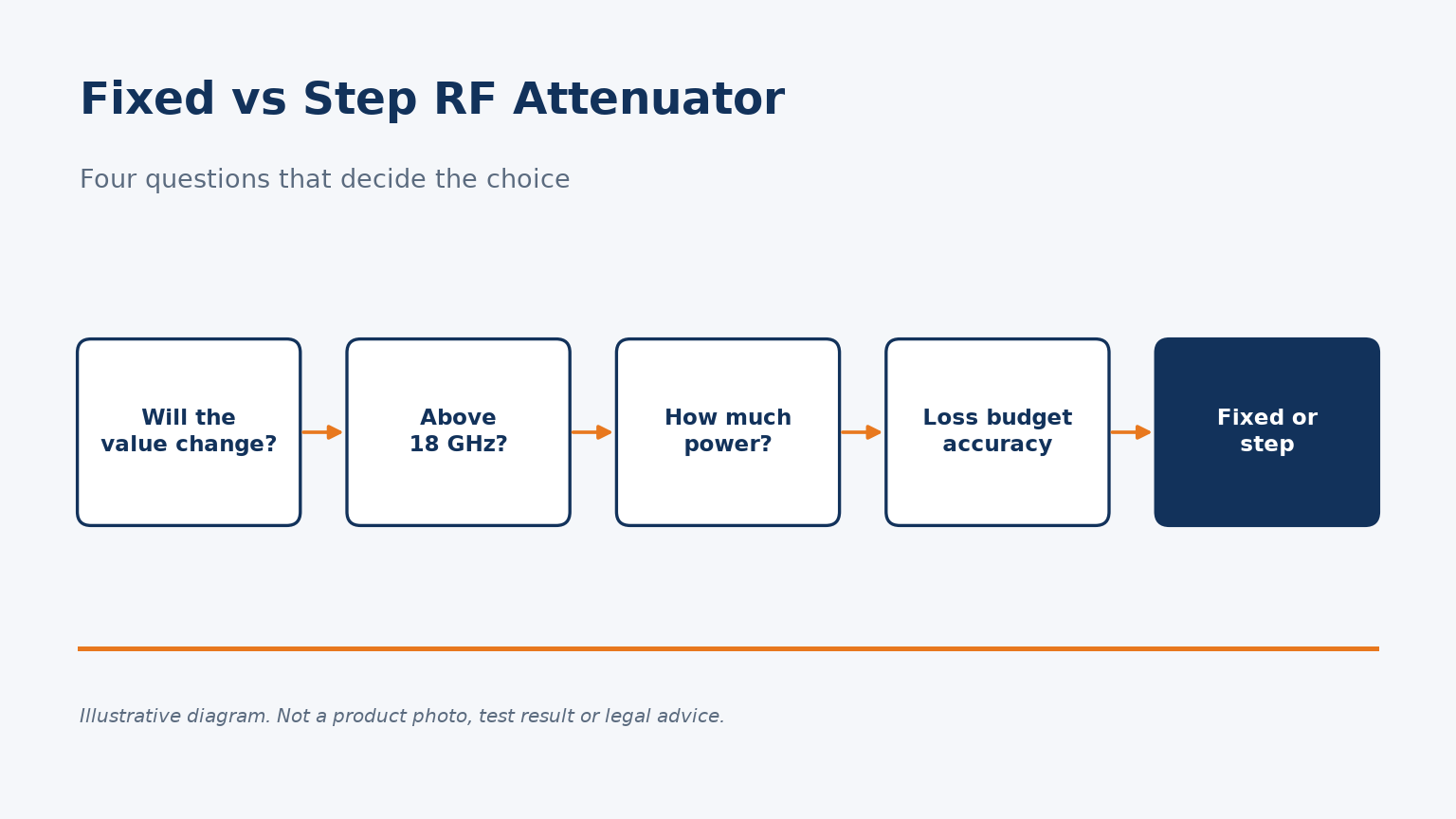
Pick the wrong attenuator type and you either swap parts all day or carry an unknown loss into every measurement.
Use a fixed attenuator when the level never changes, the frequency is above 18 GHz or power is high. Use a step attenuator when you need to change levels on the bench, remembering its dial shows change from 0 dB, not total loss.
Here is how the two compare on specification, accuracy and application.
What is the real difference between a fixed and a step attenuator?
Both reduce signal power in a 50 ohm line. They differ in how many values you get and what you give up for that flexibility.
A fixed attenuator gives one calibrated value in a small, passive two-port. A step attenuator lets you switch between many values, for example 0 to 99 dB in 1 dB steps, at the cost of size, residual insertion loss and a narrower frequency range.
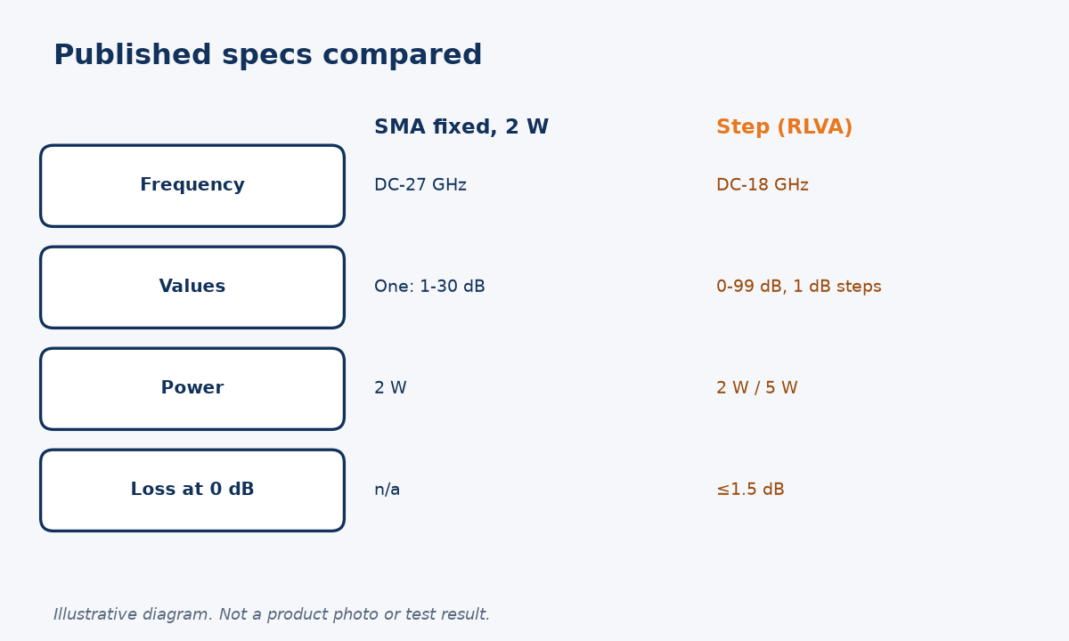
Two products, two jobs
If you are new to the component itself, our explainer on what an RF attenuator is and how it works covers the basics. Here I compare the two families using the published specifications of parts on our own site, so the numbers are concrete rather than generic.
| Parameter (as published) | SMA fixed attenuator, 2 W | Step attenuator (RLVA) |
|---|---|---|
| Frequency range | DC to 27 GHz | DC to 18 GHz |
| Attenuation | One value: 1-9, 10, 20 or 30 dB | 0 to 99 dB in 1 dB steps |
| Power | 2 W | 2 W or 5 W |
| Insertion loss at 0 dB | Not applicable | 1.5 dB max |
| Size / weight | Compact in-line body | Ø48 x 163 mm, 480 g |
Sources: the SMA 2 W fixed attenuator and the adjustable step attenuator product pages. The step attenuator is offered with SMA, N or 2.92 mm connectors, but its published range stops at 18 GHz in every case.
The national metrology lab treats these as separate device classes too. The NIST calibration services guide lists its attenuation services as "Coaxial Fixed and Variable Attenuators", and the older NBS SP 250-32 explains that variable and step attenuators are calibrated for incremental attenuation rather than a single absolute value. That distinction matters more than most buyers expect, and it is the subject of the next section.
Why does a step attenuator's dial setting not equal the total loss?
Engineers often read the dial, write down the number and forget the loss that was already there at zero.
A step attenuator is specified for incremental attenuation, the change from its 0 dB reference. Total path loss is roughly residual insertion loss plus the dial value, so a part with 1.5 dB maximum residual loss can add up to 1.5 dB beyond the dial.
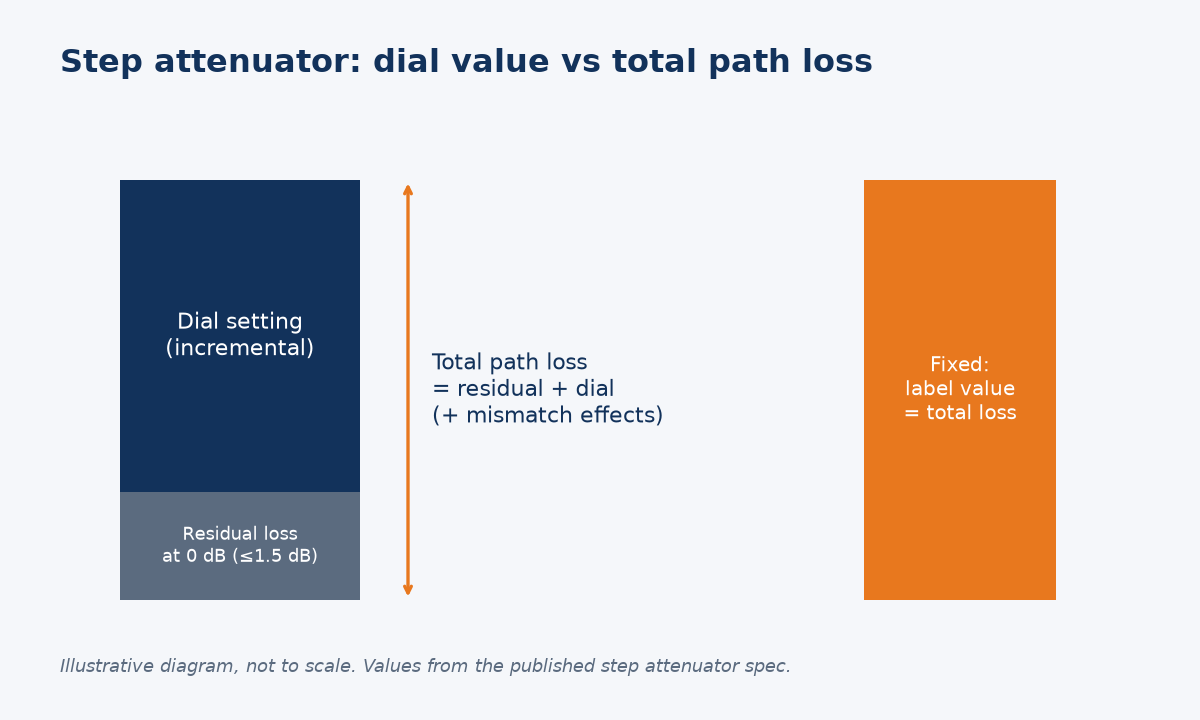
Incremental attenuation versus total loss
NBS SP 250-32 defines incremental attenuation as "the change in attenuation of a variable attenuator between a reference setting (usually zero) and any other setting". It also states that the zero setting, or another specified setting, is used as the reference during calibration. In other words, the dial calibration is relative. It says nothing about the loss of the attenuator body itself.
On our step attenuator the published insertion loss is 1.5 dB maximum. My practical reading is this: if you set 20 dB, plan for somewhere between 20 dB and about 21.5 dB in the path, plus the effect of mismatch, until you measure it. For a receiver sensitivity test that difference can move your result by more than your pass margin.
The same NBS document sets a demanding acceptance condition: variable and incremental (step) attenuators must have a repeatability of 0.01 dB or better before they are accepted for calibration. That tells you which specification to ask a supplier for when settings will be switched many times. Ask for the step accuracy and repeatability, not only the range.
A fixed attenuator does not have this trap. Its nominal value is the full insertion loss of the part, within its stated tolerance, so the number on the label is the number in your loss budget.
How do mismatch and repeatability affect attenuator accuracy?
Even a perfectly calibrated attenuator reads differently once real connectors and imperfect source and load matches are involved.
Mismatch between the attenuator and the system adds uncertainty that grows with both VSWRs, and for a variable part it changes as the setting changes. Connector repeatability adds random error every time you mate. Fixed parts in permanent paths minimise both effects.
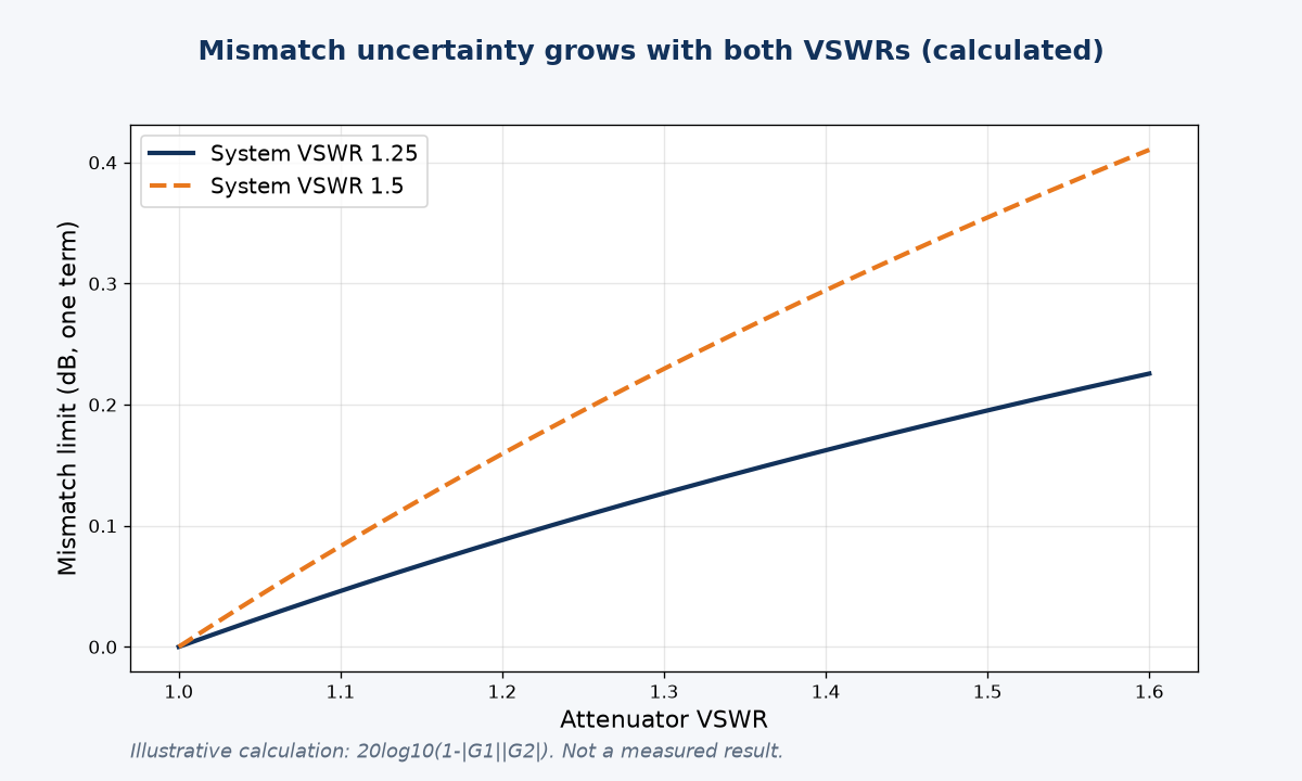
Numbers you can estimate before buying
A classic paper in the Journal of Research of the NBS notes that the mismatch error when calibrating a variable attenuator depends on the reflections of the system and "upon the changes in characteristics of the attenuator as its dial is moved from the reference position". So a step attenuator does not carry one fixed mismatch error; it can differ from setting to setting.
You can estimate the size of a single mismatch term with the standard limit 20 log10(1 ± |Γ1||Γ2|). The table uses VSWR values from our product pages and an assumed 1.5:1 system port.
| Attenuator VSWR | System VSWR | Approximate mismatch limits |
|---|---|---|
| 1.25 (SMA 2 W fixed) | 1.25 | +0.11 / -0.11 dB |
| 1.25 (SMA 2 W fixed) | 1.5 | +0.19 / -0.20 dB |
| 1.35 (2.92 mm 50 W fixed) | 1.5 | +0.26 / -0.26 dB |
| 1.45 (SMA 50 W fixed, at 18 GHz) | 1.5 | +0.31 / -0.33 dB |
These are calculated limits for one interaction, not measured results. Connectors add a second, random contribution: NIST researchers describe connector repeatability errors as the primary source of random errors in coaxial power and S-parameter measurements. In my experience that is the strongest argument for leaving a fixed attenuator installed in a test path instead of swapping parts. If you need to verify a part yourself, our guide on how to test the accuracy of an RF attenuator walks through the VNA S21 and S11 method, and VSWR vs return loss explains the conversion.
Which attenuator type should you choose for your application?
The choice usually comes down to three questions: will the value change, how high is the frequency, and how much power is involved.
Choose a fixed attenuator for production test stations, permanent paths, high power and anything above 18 GHz. Choose a step attenuator for bench work, sensitivity sweeps and prototypes where you need to change the level often, up to 18 GHz and 5 W.
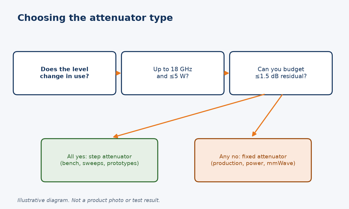
A simple decision rule
| Your situation | Better fit | Why |
|---|---|---|
| Value changes during the test | Step attenuator | One part covers 0-99 dB |
| Fixed level in production or a system | Fixed attenuator | Label value is the total loss; no switching |
| Above 18 GHz | Fixed attenuator | Our step range is DC-18 GHz; fixed parts go to 40, 50 and 67 GHz |
| Tens of watts | Fixed attenuator | For example 50 W SMA (DC-18 GHz) or 50 W 2.92 mm (DC-40 GHz) |
| Tight loss budget | Fixed, or measure the step part | Residual loss up to 1.5 dB at 0 dB |
For high power, compare the 50 W SMA fixed attenuator with the 50 W 2.92 mm fixed attenuator. For millimetre-wave paths, see our high-frequency fixed attenuators. The full range is in the fixed attenuator category.
A pattern I recommend to customers is to use both: a step attenuator on the development bench to find the level that works, then a fixed attenuator of that value, or a combination of two, on the production station. You keep the flexibility where it saves time and remove the switching uncertainty where it costs yield. It also simplifies documentation, because a fixed part has one value to verify at incoming inspection instead of a hundred settings.
If you are not sure which value, power rating or connector you need, send us your frequency range, input power and connector type through our contact page. We will recommend a part number and quote it, and we can share datasheet values for the specific model you choose.
Conclusion
Fixed for stable, high-power or mmWave paths; step for bench flexibility to 18 GHz. Tell us your band, power and connector for a quote.
STAY IN FOR MORE NEWS
Subscribe to our free newsletter.
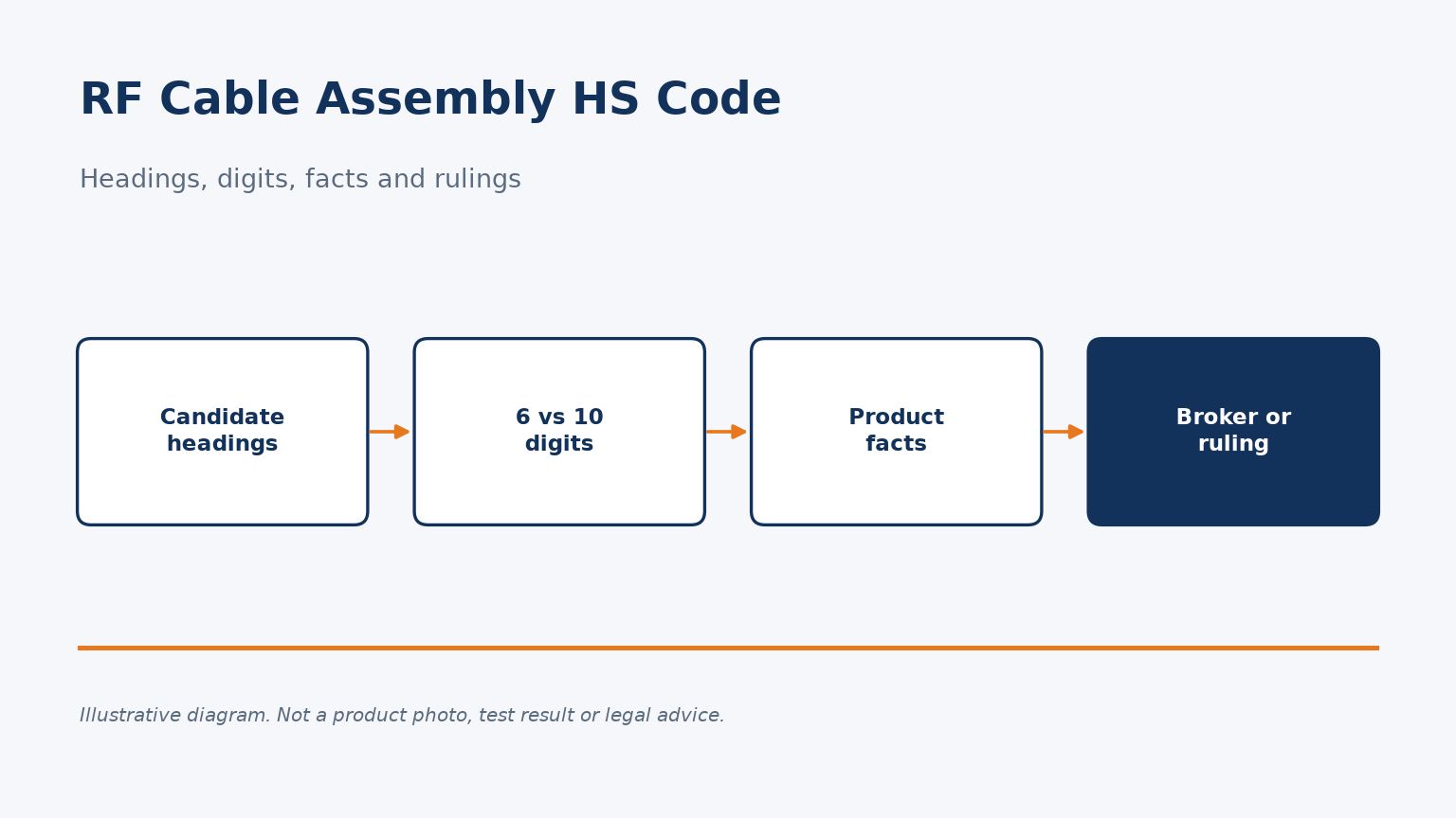
Which HTS headings are considered for RF cable assemblies, why six digits are not enough, which facts matter, and how to get a reliable classification.
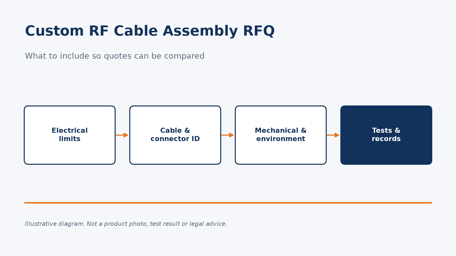
A checklist for custom RF cable assembly quote requests: electrical limits, part identity, mechanical and environmental details, and test records.
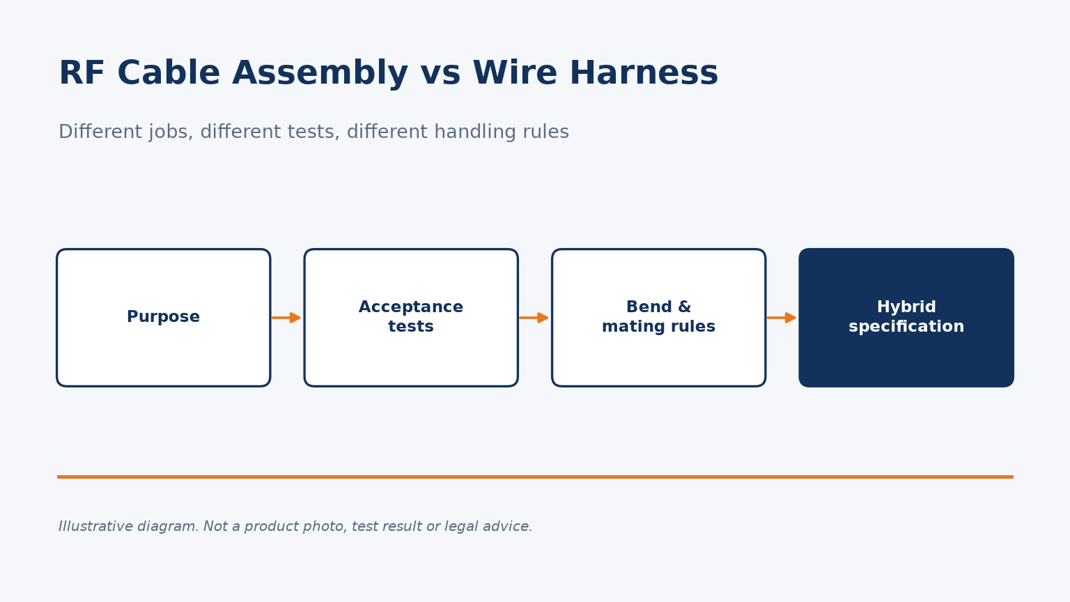
RF cable assemblies and wire harnesses differ in purpose, acceptance tests, bend limits and interfaces. Here is how to specify each, and hybrids.
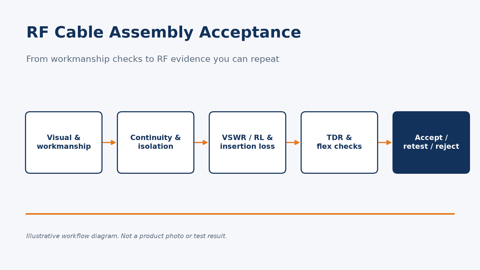
Which tests, conditions and retest rules turn an RF cable assembly quality check into acceptance evidence you can repeat.
