
by Angela
Share
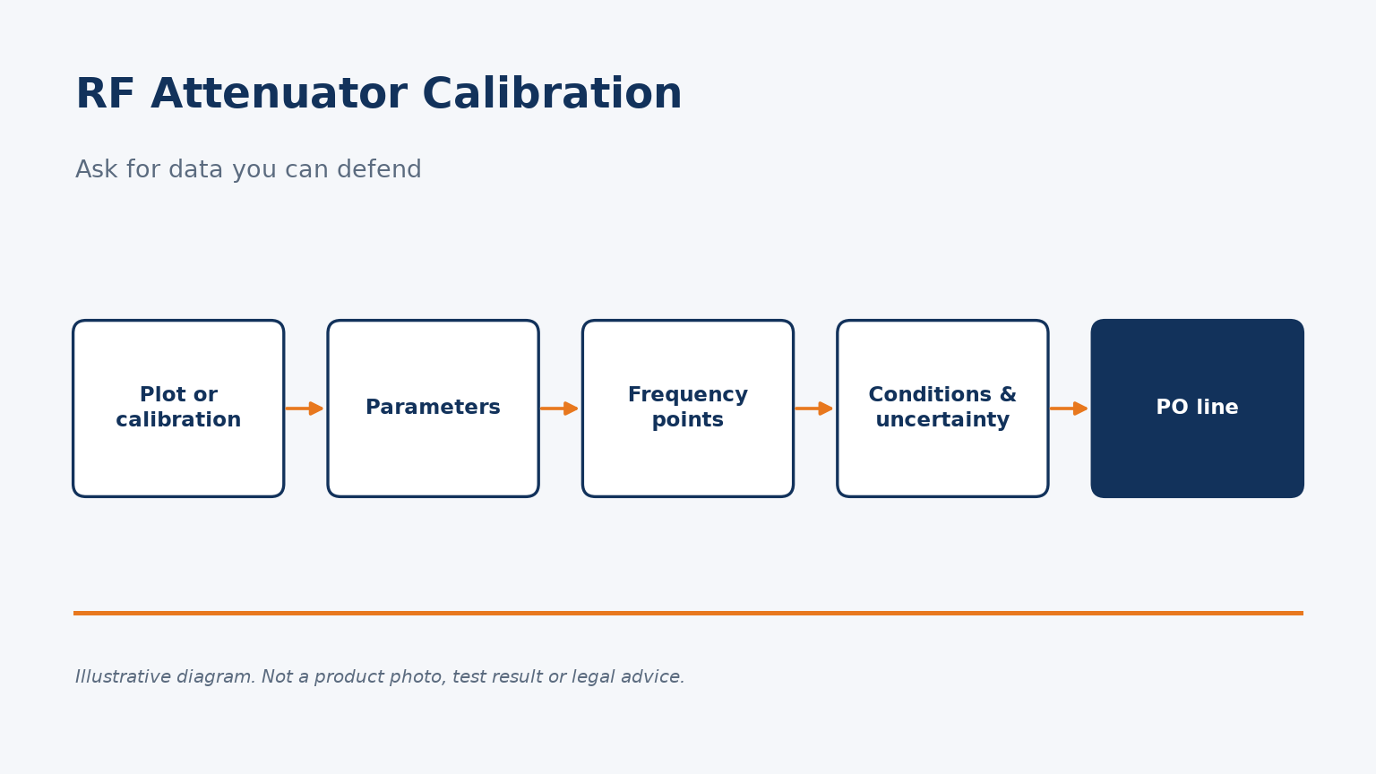
A shipping box that contains “a plot” is not the same as a calibration you can defend in an audit.
Request RF attenuator calibration as named parameters at stated frequencies and conditions, and say whether you need a factory plot or a formal calibration with uncertainty. For step attenuators, ask for incremental attenuation from a reference setting, not only a single loss figure.
Below I compare those options and give a PO checklist; or send the part and the data you need and we will say what we can provide.
What is the difference between a factory test plot and a calibration?
Both are useful, but they are not interchangeable, and the purchase order should say which one you are buying.
A factory test plot shows that a unit was measured against the supplier’s own process. An RF attenuator calibration is a measurement of specified parameters at stated frequencies and conditions, often with an uncertainty, and sometimes by an accredited laboratory. Ask for the one your process actually requires.
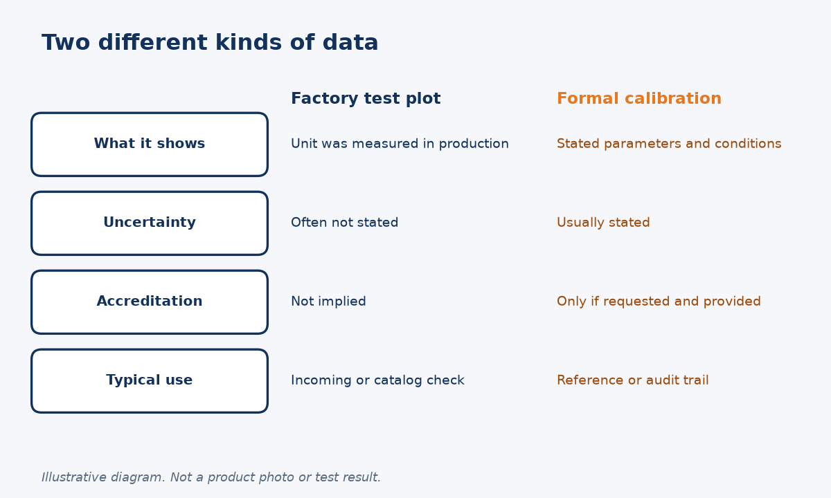
Do not assume a plot is a certificate
Many attenuator product pages, including our own, mention a test plot as part of the listing. That is evidence the part was looked at. It is not, by itself, a statement of uncertainty, a list of frequency points, or a claim that a national laboratory would accept the instrument as a standard.
NBS Special Publication 250-32 describes coaxial and waveguide attenuation calibration services: what is being measured, how variable devices are treated, and how demanding the laboratory’s acceptance conditions are. That document is about a metrology service, not about a factory production test. I use it here as the reference for what “calibration” means when a buyer asks for it, not as a claim that every Reach Line attenuator ships with that service.
Our articles on how to test RF attenuator accuracy and on reconnection and measurement repeatability are about work you may do on the bench. This page is about what to put in the purchase order so the supplier (or a lab) knows whether you want a production plot, a manufacturer’s measurement report, or a formal calibration.
I will not claim an accreditation, a logo or a turnaround time that the site does not state. If you need an accredited calibration, write that in the RFQ and we will tell you whether we provide it, whether it must go to a third-party lab, or whether a factory plot is what we can offer.
Need an RF attenuator and want the data defined up front? Send the dB value, band, connectors and the kind of data you need, or start from a catalog part such as the N type 5 W fixed attenuator and add the measurement requirement.
What data belongs on an RF attenuator calibration report?
If the report does not name the parameter, the frequency points and the conditions, it is hard to use later.
Ask for attenuation (and, if you need it, return loss or VSWR) at stated frequencies, the port configuration, the temperature, the instrument or method, and an uncertainty if the work is a formal calibration. A single “pass” stamp without those items is weak evidence.
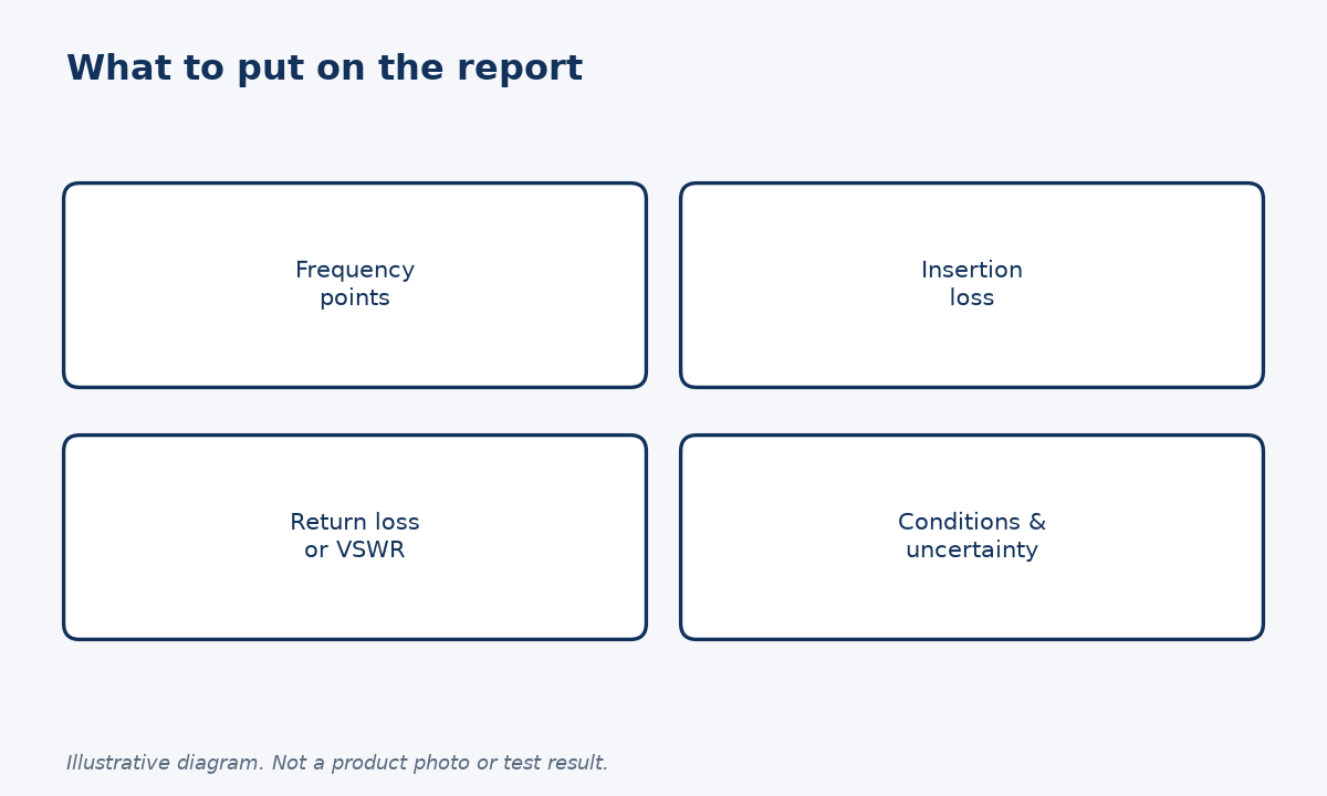
Frequency points and parameters first
Attenuation changes with frequency, so a report that only says “20 dB, passed” does not tell you the value at your band edges. I would list the frequency points you care about, or ask for a sweep with enough points to see the worst case. If mismatch matters in your setup, also ask for return loss or VSWR at both ports, or at least at the port that will face a sensitive instrument.
Conditions belong next to the numbers. Temperature, input power used for the measurement, and whether the figures are incremental or absolute (see the next section) all change how you read the report. The NBS mismatch paper is a reminder that the measured attenuation of a variable device also depends on the system match and on how the device itself changes between settings. Even for a fixed pad, the system match during the test should be honest, and a stated VSWR on the part helps you estimate residual error.
A formal calibration usually includes an uncertainty. A factory plot often does not. Neither is “wrong,” but they support different decisions. Incoming inspection against a wide catalog tolerance may need only a plot. Using the attenuator as a reference in a measurement chain is closer to a calibration problem.
If you will keep the report with the part, ask for the serial number on both the body and the document. A plot that cannot be tied to a unit is of little help a year later.
When do fixed and step attenuators need different calibration terms?
The same word “attenuation” does not mean the same quantity on a fixed pad and on a step or variable unit.
For a fixed RF attenuator, you usually want the actual insertion loss at stated frequencies. For a step or variable attenuator, calibration is typically incremental attenuation from a reference setting, plus residual insertion loss at that reference, and a repeatability figure if settings will be changed often.
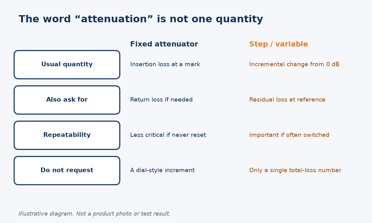
Incremental versus total loss is a purchase-order issue
NBS SP 250-32 explains that variable and step attenuators are treated in terms of incremental attenuation, the change from a reference setting (usually zero), and that the laboratory’s acceptance condition for those devices included a repeatability of 0.01 dB or better. That 0.01 dB figure is a calibration-service acceptance criterion from the document, not a Reach Line product specification, and I will not present it as one. It is still the right idea to put in an RFQ when a step attenuator will be used as a variable standard: ask for incremental accuracy and repeatability, not only the 0-to-99 dB range.
We used the same distinction in fixed vs variable (step) RF attenuators. On our step-attenuator listing, the published insertion loss at 0 dB is a residual that has to be added to the dial. If you request “calibration” without saying incremental versus absolute, one supplier may report dial error only and another may report total path loss. Those reports will not compare.
For a fixed pad, the request is simpler: insertion loss at the marked value and frequencies, and return loss if you need it. Our 5 W N-type fixed attenuator and the wider fixed attenuator range are the catalog starting points. For reconnection effects that show up when you repeat a measurement, see the repeatability article.
If you are unsure which kind of report to ask for, tell us how the attenuator will be used — a permanent pad in a chain, or a stepped standard on the bench — and we will recommend the data, not just the hardware.
What should you request in the purchase order for RF attenuator calibration?
A short, explicit data line prevents a “plot included” shipment when you thought you had ordered a calibration.
Write the parameters, frequency points, conditions, whether the work is a factory plot or a formal calibration (and any accreditation you require), and whether you need a serialised report. Also include the usual hardware items: connectors, dB value, band, power and quantity.
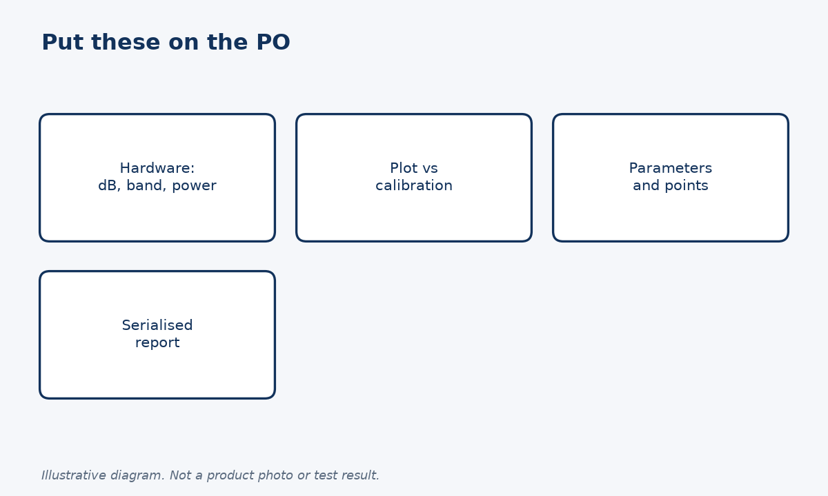
A checklist you can paste into the RFQ or PO
| RFQ line | What to state |
|---|---|
| Hardware | Connectors, dB value, band, power, quantity |
| Data type | Factory plot, manufacturer report, or formal calibration |
| Parameters | Insertion loss; return loss or VSWR if needed |
| For step units | Incremental attenuation, residual loss, repeatability |
| Points and conditions | Frequencies, temperature, port configuration |
| Records | Serial number on part and document; uncertainty if calibrated |
If your quality system requires an accredited laboratory, name that requirement. If a factory plot is enough, say “factory test plot, no accredited calibration required.” Either line is clearer than “please calibrate.”
When you are ready, request a quote with frequency range, connector types, attenuation value, quantity, the application, and the data you need. We will tell you what we can provide with the part and what would have to be arranged separately. We will not imply a laboratory accreditation that we have not stated.
It is worth adding one process note. Keep the report with the serialised part, and record the date. An attenuator that later fails incoming, or that is dropped and re-tested, is much easier to handle if the original numbers are still attached. If you only asked for a loose plot with no serial, you cannot close that loop.
If several values are being bought together — for example 10 dB and 20 dB pads in the same N 5 W family — ask for the same frequency points and the same report type on every line. Mixed evidence, where one unit has a plot and another has a formal calibration, makes later audits harder than they need to be.
Finally, tell us if the attenuator will be used as a working standard or only as a set-and-forget pad. The first case is where incremental data, repeatability and uncertainty earn their keep. The second case is often well served by a factory plot and a clear catalog tolerance.
Frequently asked questions
Is a factory test plot the same as an RF attenuator calibration? No. A plot shows the unit was measured. A calibration states parameters, conditions and, usually, an uncertainty. Ask for the one your process requires.
What frequency points should I request? List the points that matter to you, including band edges, or ask for a sweep dense enough to show the worst case. A single “passed” mark is not enough to reuse later.
How is a step attenuator calibrated differently from a fixed pad? Step and variable units are typically reported as incremental attenuation from a reference setting, plus residual insertion loss. A fixed pad is reported as insertion loss at the marked value.
Does Reach Line provide accredited calibrations? Do not assume an accreditation from this article. Tell us in the quote request if you need an accredited laboratory report, and we will say what we can provide or arrange.
Conclusion
Name the parameters, the frequency points and whether you want a plot or a formal calibration; then the RF attenuator data can be audited.
STAY IN FOR MORE NEWS
Subscribe to our free newsletter.
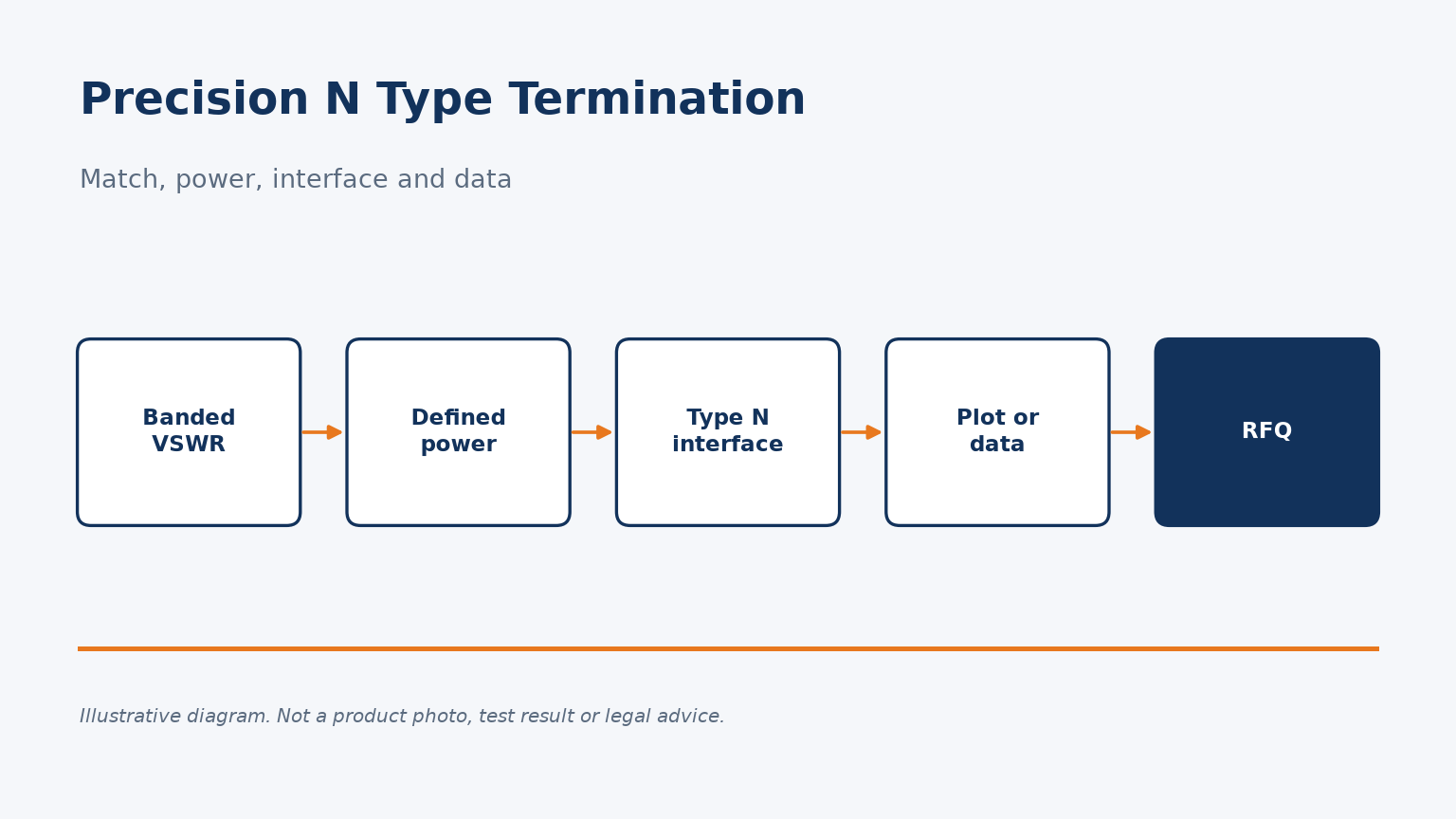
A precision N type termination is defined by banded VSWR, power and data, not a label. See what to request besides a catalog 18 GHz Type N load.
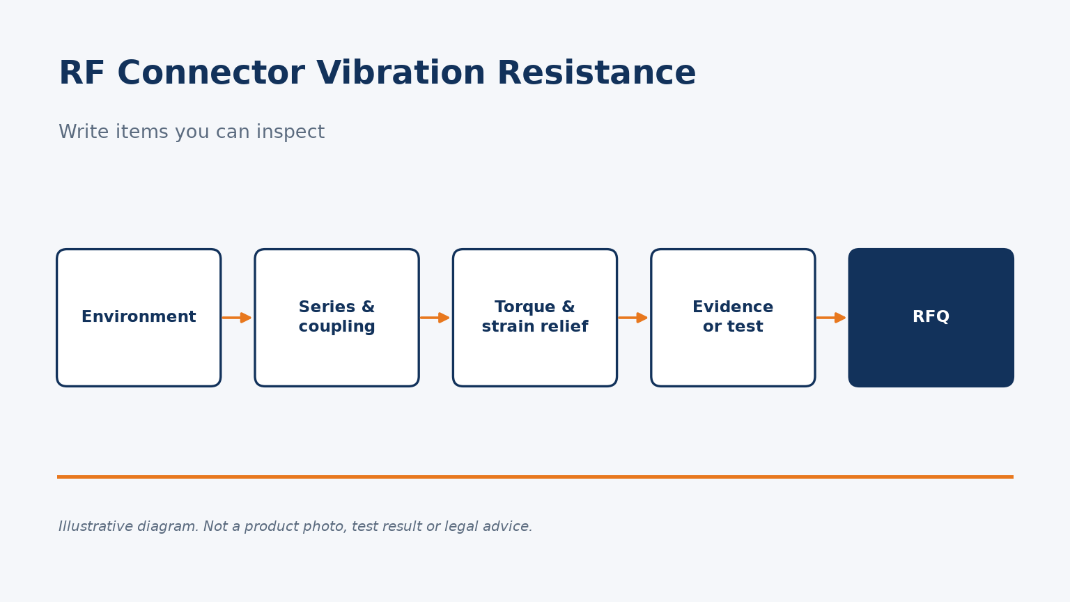
Vibration resistance is not a part number. Specify coupling style, torque, strain relief and the test method in your RF connector or cable RFQ.
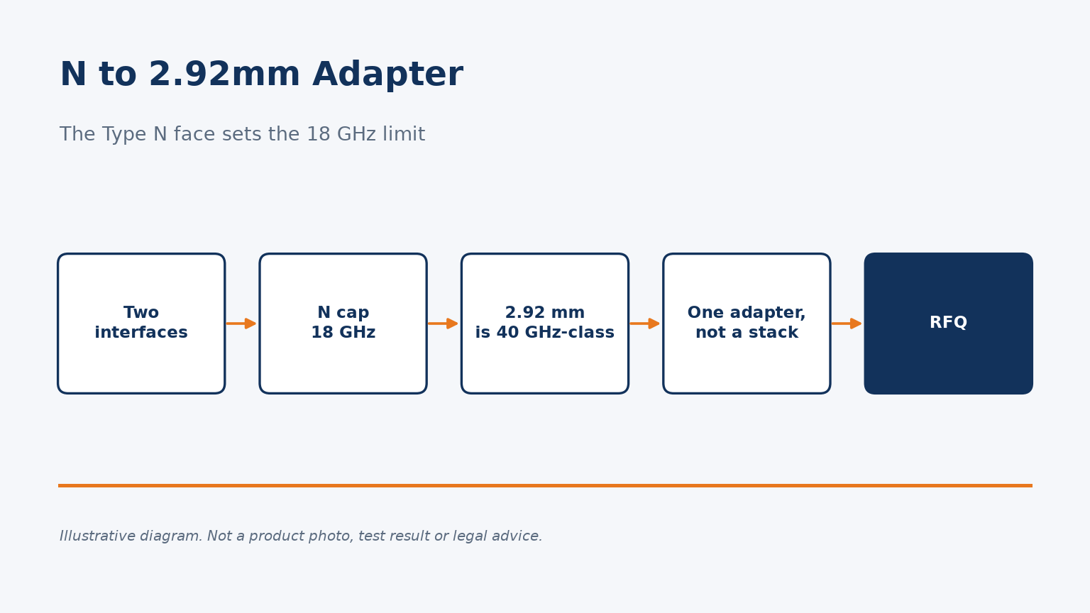
An N to 2.92mm adapter is limited by the Type N side, usually to 18 GHz. Do not expect a 40 GHz path. See genders, VSWR and a short RFQ list.
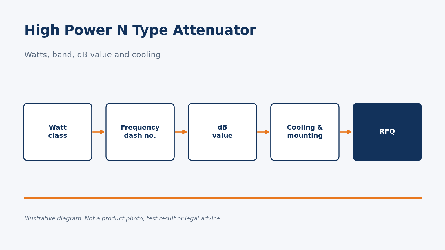
A high power N type attenuator RFQ needs wattage, band, VSWR, dB value and cooling. Compare published 5 W and 250 W listings before you buy.
