
by Angela
Share
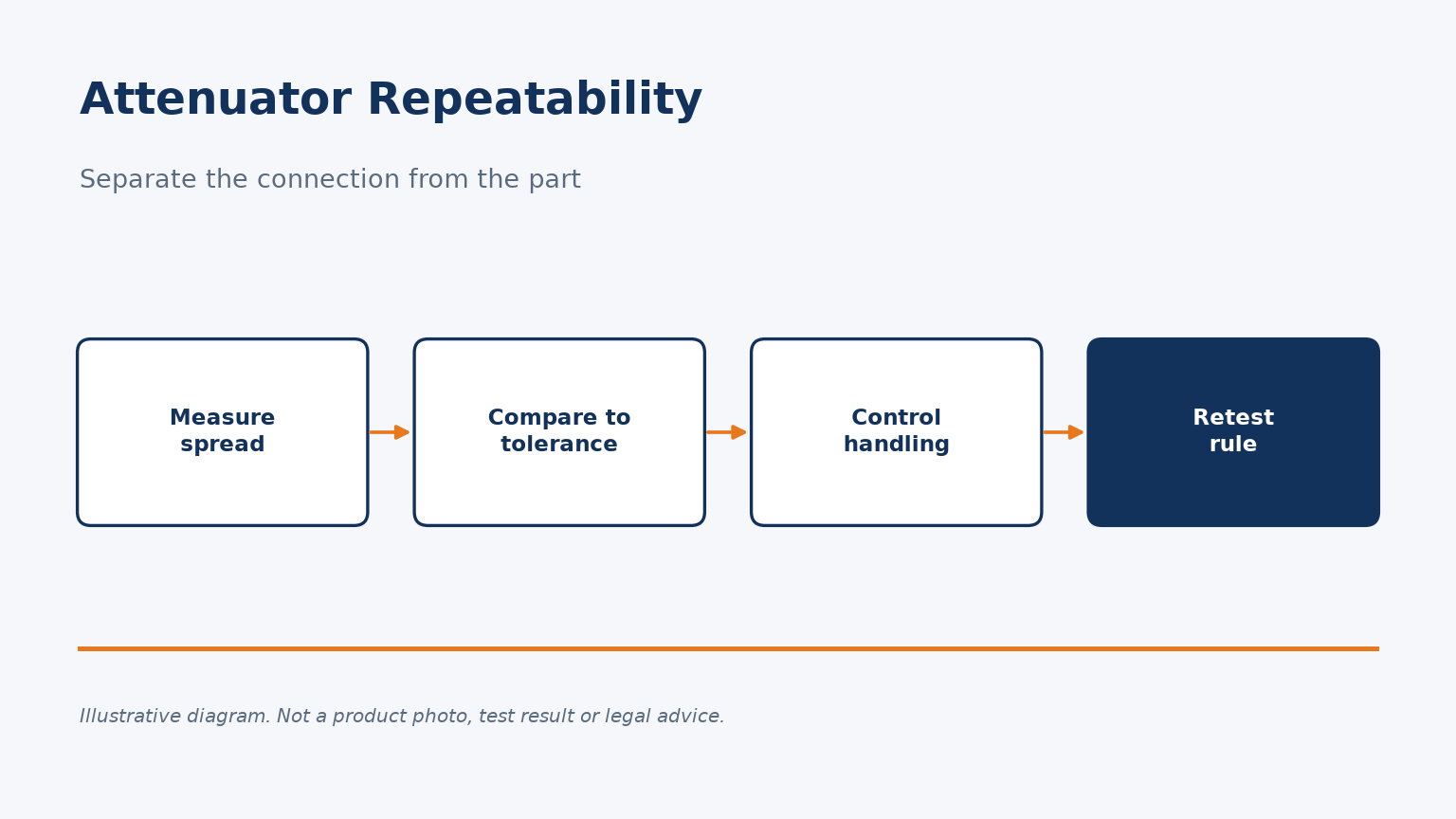
An attenuator that reads differently every time you reconnect it is usually telling you about the connection, not the part.
Reconnection changes attenuator readings because each mating seats the contacts differently. Measure your setup's reconnection spread, control torque and handling, and agree a retest rule before judging parts near the tolerance limit.
Below I explain how to size and reduce that spread; if your readings are inconsistent now, send us your data.
Why does the same attenuator read differently each time you reconnect it?
Measure a fixed attenuator, disconnect it, reconnect it, and the reading moves. The attenuator has not changed; the connection has.
Each mating seats the contacts slightly differently, changing contact resistance and the small reflections at each interface. NIST identifies connector repeatability as the primary source of random error in coaxial measurements, so reconnection spread can rival the tolerance you are trying to verify.
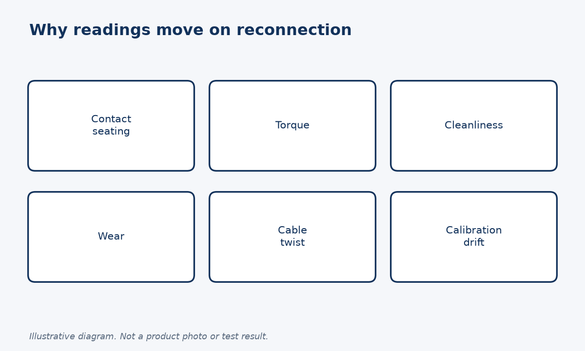
The connection is part of the measurement
NIST research by Lewandowski and Williams states that connector repeatability errors are the primary source of random error in coaxial power and S-parameter measurements. For attenuator testing, that means a share of what looks like attenuator variation is actually variation in how the two interfaces were mated on that occasion.
The effect is largest when the attenuation tolerance is tight relative to the measurement, at higher frequencies, and with worn or dirty connectors. It is smallest for large attenuation values measured with plenty of margin, where a few hundredths of a dB do not change the decision.
My practical reading is that a single connect-measure-disconnect reading is not enough to judge a part close to its limit. You need to know how much of the spread belongs to the connection before you blame the attenuator. Our existing article on how to test attenuator accuracy covers the measurement method; this one focuses on the reconnection part. If a batch of our SMA fixed attenuators (RLAS2 series) reads inconsistently on your bench, send us the data and we will help separate setup effects from part behaviour.
How large is reconnection spread compared with attenuator tolerance?
Whether reconnection spread matters depends on the ratio between that spread and the tolerance you are checking.
There is no universal figure; it depends on connector type, condition, torque and frequency. Measure it on your own setup by reconnecting a known part several times, then compare that spread with your acceptance tolerance before judging any part.
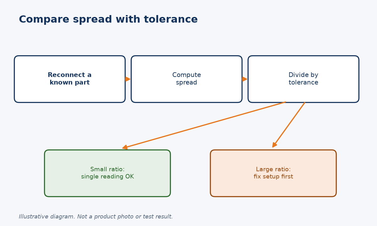
A reference point from calibration practice
The old National Bureau of Standards attenuation calibration service, described in NBS SP 250-32, only accepted variable and step attenuators whose repeatability was 0.01 dB or better. That number is a calibration-lab acceptance criterion, not a product specification, but it shows how seriously metrologists treat repeatability before they trust an attenuation value.
| Ratio of spread to tolerance | Practical meaning |
|---|---|
| Small (well under one tenth) | Single readings are usually fine |
| Moderate | Use averaged readings near limits |
| Large (approaching tolerance) | Fix the setup before judging parts |
The ratios in the table are a rule of thumb I use, not a standard. The point is to estimate your setup's spread, then decide how many readings a pass/fail decision needs. A simple way to estimate spread is to reconnect one known attenuator five to ten times at your critical frequency, using normal handling, and record the range of results. Repeat it after changing operator or cable to see which factor dominates. If you buy attenuators against a tight tolerance, it is reasonable to ask the supplier how they handle results near the limit; for Reach-line parts, contact us and we will explain our test approach for the specific value you need.
Which bench practices reduce reconnection error?
Most reconnection spread comes from handling, not from the attenuator. A few habits remove much of it.
Use a calibrated torque wrench, turn only the coupling nut, keep connectors clean and gauged, support cables so they do not twist the interface, use connector savers on instrument ports, and record the configuration so the setup can be repeated.
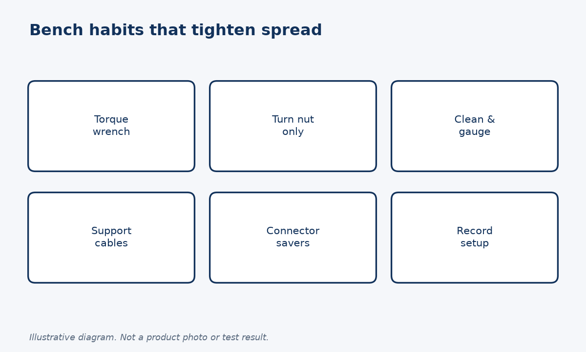
Habits that tighten the spread
Torque is the first control. NASA-STD-8739.4A says coaxial mating torque should come from engineering documentation, with the connector manufacturer's value recommended, and that only the coupling nut should be turned. Turning the body twists the centre contact and wears both interfaces, which adds variation every time.
Cable support is second. A test cable that hangs from the attenuator or rotates as it is tightened changes both the mating and the cable's own phase and loss. Supporting it and keeping the same routing between readings removes a large source of drift.
Connector condition is third. Dirt, metal particles and worn contacts increase both loss and variability; interface dimensions are defined in MIL-STD-348 and gauging confirms parts are within them. A connector saver on the instrument port moves the wear to a cheap, replaceable part. In my experience, applying these three habits consistently matters more than any single expensive accessory, and it costs almost nothing.
How should buyers handle attenuator results near the limit?
Borderline readings cause most disputes between buyers and suppliers. A written rule settles them before they happen.
Agree in advance on test frequency points, torque, calibration method and a retest rule: for example, reconnect and remeasure several times and judge on the average. Ask the supplier to state their test conditions so both sides can reproduce the result.
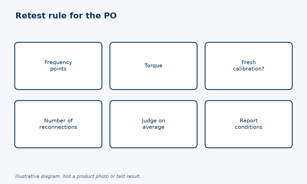
Write the retest rule into the order
NIST work by Koepke and Jargon separates random variation in repeated S-parameter measurements into components from calibration, disconnect and reconnect, and repeat measurements. The practical consequence is that one reading combines several sources of variation, and averaging repeated connections reduces only some of them. A sensible retest rule therefore specifies both the number of reconnections and whether a fresh calibration is required.
When ordering, state the attenuation value, the frequency band, the tolerance and the conditions behind it. Our RLAS2 series listing gives SMA interfaces, DC to 27 GHz (26.5 GHz in the model table), 2 W average power, values of 1 to 10, 20 and 30 dB, VSWR 1.25 and -55 °C to +125 °C operating range; ask us for the tolerance of the specific value you need.
For a broader comparison of attenuator types, see fixed vs variable step attenuators. When you are ready, request a quote or open the RLAS2 SMA attenuator page to choose the value.
Conclusion
Measure your reconnection spread, control handling, and agree a retest rule; then attenuator readings become evidence both sides trust.
STAY IN FOR MORE NEWS
Subscribe to our free newsletter.
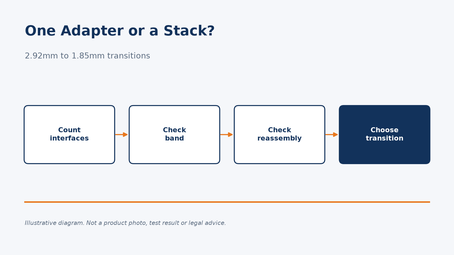
When to use one 2.92mm to 1.85mm transition adapter instead of an adapter stack: loss, reflection ripple, repeatability and how to order.
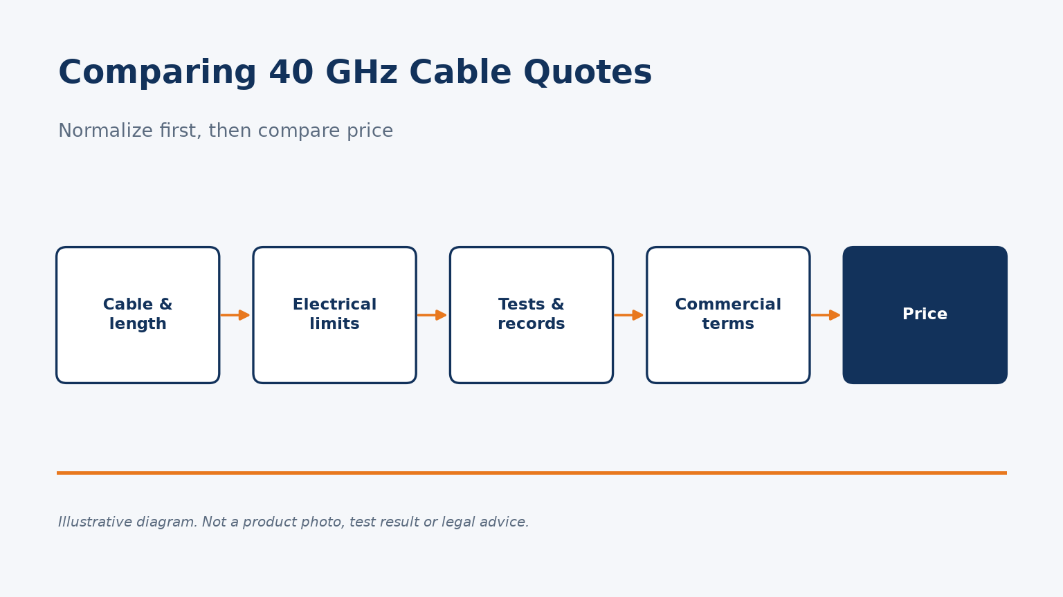
How to compare 2.92mm 40 GHz cable assembly quotes fairly: normalize cable, length, guaranteed limits, test records and commercial terms.
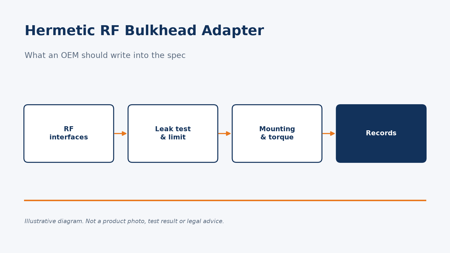
What OEM buyers should specify for a hermetically sealed RF bulkhead adapter: leak-test method and limit, mounting, torques and records.
How to specify RF termination power for CW and pulsed signals: average vs peak, duty cycle, temperature derating, and an RFQ checklist.
