by Angela
Share

RF vs. Microwave vs. Millimeter-Wave: What’s the Difference?
Confused about which frequencies power your tech? Using the wrong components can lower performance and cause system failures. This guide clears up the terminology so you can find the right solutions.
RF, microwave, and millimeter-wave describe frequency ranges with distinct uses. RF covers 3 kHz to 300 GHz, including microwaves and mmWave. Microwaves occupy 300 MHz to 300 GHz, while mmWave strictly focuses on 30 GHz to 300 GHz. Each handles specific tech needs.
Understanding these differences is key to choosing the right connectors, antennas, and systems. Let’s dig deeper into their unique roles.
What is the difference between RF and microwave?
Mixing RF and microwave terms can lead to selecting parts that don’t work. This differentiation protects your system integrity.
RF (Radio Frequency) includes all electromagnetic frequencies from 3 kHz to 300 GHz. Microwave is a subset within that range (300 MHz to 300 GHz). The main difference is their applications: RF handles a broad range of signals like radios, while microwaves focus on high-frequency uses like radar and satellites.
Frequency Ranges and Use Cases
RF spans an enormous range, from AM radio (kHz) to 5G cellular signals (mid GHz). These lower and mid-range frequencies travel far but carry limited data. For example, a broadcast antenna uses RF frequencies to send signals over long distances.
Microwaves occupy the higher end starting at 300 MHz. Their shorter wavelengths allow:
- Higher data speeds (satellite internet)
- Sharper precision (radar systems, cancer treatment)
- Bands like 5G millimeter-wave (if within their range)
Our products include connectors and waveguides optimized for microwave bands where precise signal handling is needed.
Physical Differences
RF hardware often uses coaxial cables (like N-Type or SMA connectors) because lower frequencies don’t need specialized conduit. Microwaves require single-mode waveguides or air-dielectric cables to maintain signal integrity. I recall working on a defense project where switching from coax (RF) to waveguide (microwave) meant 80% less signal loss at 24 GHz.
| RF | Microwave |
|---|---|
| Frequencies: 3 kHz–300 GHz | 300 MHz–300 GHz |
| Typical use: Broadcasting, cellular | Radars, satellite, Wi-Fi 6E |
| Wavelength: Longer | Shorter wavelengths |
| Components: Coax, bulkhead connectors | Waveguide sections, E-plane bends |
What is the difference between mmWave and microwave?
Calling them the same can cause costly errors in selecting components or designing systems. Let’s clarify.
Microwaves include mmWave as their upper range (30–300 GHz). The distinction is that mmWave:
- Uses frequencies beyond cellular 4G (starts at ~24 GHz)
- Requires special components to handle short wavelengths
- Offers ultra-fast data at shorter ranges
Tuning into Higher Frequencies
Moving from microwave to mmWave is like upgrading from marathon runners to sprinters:
- Bandwidth: mmWave carries 40x more data per second
- Antennas: Need precision manufacturing (e.g., 2.92mm connectors vs 1.85mm for higher GHz)
- Range: A 10-meter pole-to-pedestrian gap can block weak links
When building a 30 GHz test system, we had to use phase-matched cables and DC blocks to prevent interference at these extremes.
Why the Distinction Matters
When selecting components:
- Microwave bands up to 24 GHz use cheaper components (e.g., WR-75 waveguide)
- mmWave requires specialized materials and tighter tolerances (varactor diodes, Vivaldi antennas)
Think of mmWave as the “high-definition” version of microwave – sharper but needing more precise tools.
| Microwaves | mmWave |
|---|---|
| Up to 300 GHz | 30–300 GHz |
| Longer range links | Short high-speed bursts |
| Satellite uplinks | 5G small cells |
| Waveguide sizes: WR-284 (30cm) | WR-2 (5mm) components |
What is the difference between RF and microwave plasma?
Choosing the wrong energy source could ruin your production process. Here’s the critical distinction.
RF plasma uses lower frequencies (up to 100 MHz) while microwave plasma uses higher GHz bands. The key difference is their energy transfer: RF works best for films and materials, while microwaves suit high-power applications.
How They Create Plasma
Plasmas require ionization. RF:
- Uses 13.56 MHz to 60 MHz for semiconductor etching
- Frequencies stay low enough for steady current flows through coils
- Best for producing uniform layers in material science
Microwave:
- Uses 2.45 GHz in systems like automotive part bonding
- Shortwaves penetrate deeper due to field strength
- Requires waveguide-fed systems for stable arcing
One challenge: RF plasma systems demand precise impedance matching to handle phase shifts, which I experienced while testing a SiC reactor.
Component Choices Matter
- RF plasma setups use air-tight loads and pinch-to-seal connectors (e.g., 3.5mm feedthrough)
- Microwave systems require waveguide joints and phase-shifting components to sustain plasma glow
The lower frequency RF plasma can be maintained even with medium vacuum, increasing design flexibility.
| RF Plasma | Microwave Plasma |
|---|---|
| Frequency: Up to 200 MHz | 1–10 GHz |
| Applications: Coating, etching | Welding, sputtering |
| System Size: Smaller footprints | Larger waveguide requirements |
What are the advantages of microwaves over radio waves?
Microwaves beat low-frequency radio in certain scenarios. Learn when to choose their higher performance.
Microwaves offer greater bandwidth capacity (10×–100× more data), smaller components, and higher resolution than radio-frequency bands below 300 MHz.
Key Advantages
- Speed/Volume:
- Allows mmWave-only 5G (20 Gbps download speeds)
- Enables 4K/8K streaming in stadiums
- Component Precision:
Microwave’s shorter wavelength (2 cm vs radio’s meters) lets engineers build miniaturized antennas and filters. For instance, 28 GHz 5G base stations use phased arrays a fraction the size of LTE antennas. - Focus Accuracy:
- Radar spots small objects (think drone avoidance systems)
- Satellite links connect micron-sized targets over continents
We once fixed a radar system by upgrading from 1 GHz to 94 GHz sensors, cutting spot size from 1m to 12cm.
Trade-Offs to Note
Yes, there are downsides:
- Less penetration through walls/materials
- Shorter transmission distances
These weaknesses make low-frequency radio better for broadcasting over wide areas (AM radio still reaches cars deep in forests
STAY IN FOR MORE NEWS
Subscribe to our free newsletter.
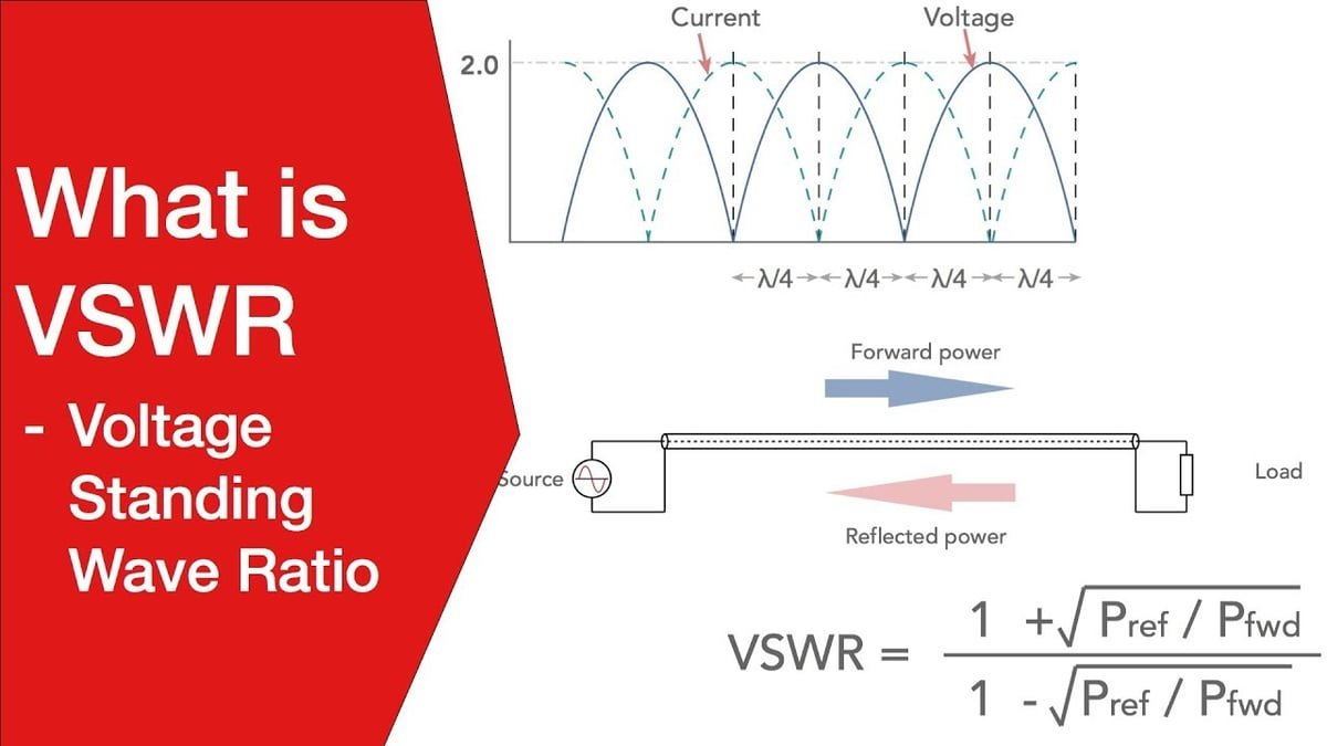
Introduction to VSWR Voltage Standing Wave Ratio (VSWR) is a critical parameter in RF (Radio Frequency) systems, indicating how effectively power is transferred from a source to a load. It measures the ratio of the maximum to the minimum voltage in a standing wave formed by reflected and transmitted signals.

The evolution of 5G technology has brought immense benefits—but also unprecedented challenges—particularly in the field of RF testing and measurement. As new technologies like millimeter wave, beamforming, and ultra-wideband become essential to 5G, traditional testing methods are no longer sufficient. Over-the-air (OTA) testing is now central to ensuring performance and compliance with 5G NR standards.
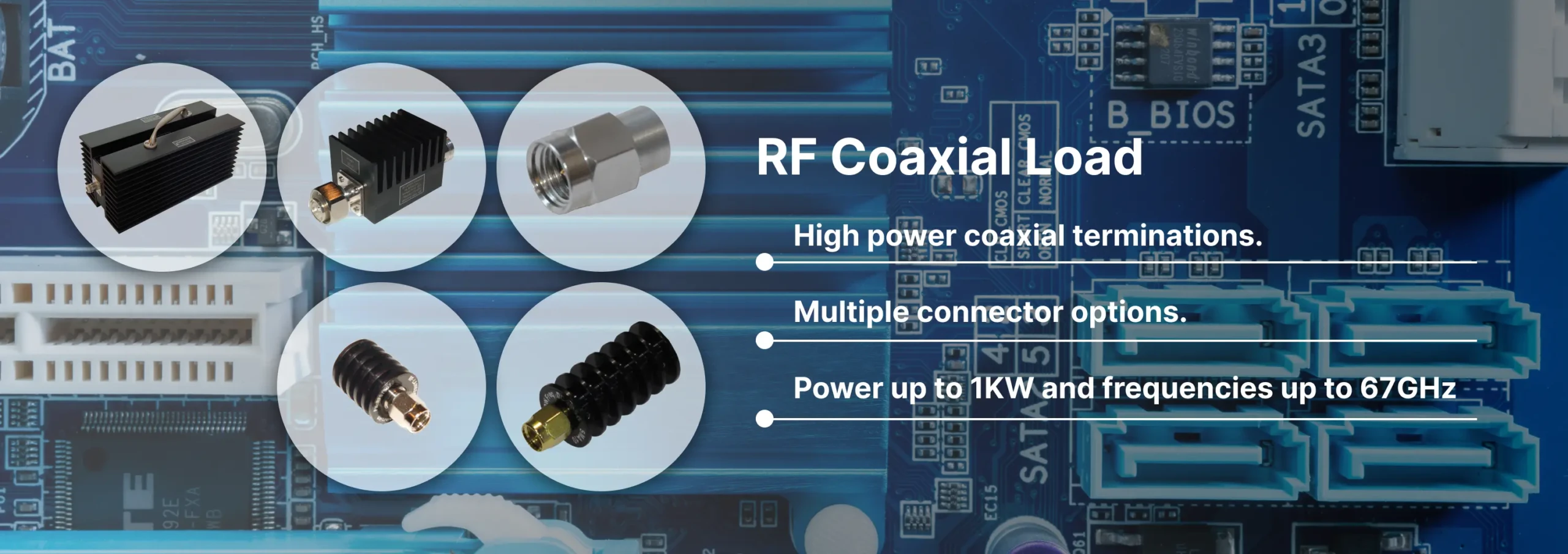
Discover Reach-Line’s precision RF and microwave terminations covering DC to 110 GHz and power levels 1 W to 1000 W. Reliable, low VSWR solutions for 5G, satellite, and lab applications.

Reach-Line offers high-frequency cable assemblies, fixed attenuators, and precision terminations. Partner for engineering support, rapid prototyping, and global logistics.